[Previous] [Next]
Working with the Bus Driver
In contrast to drivers for devices that attach to traditional PC buses such as PCI
(Peripheral Component Interconnect), a USB device driver never talks directly to its hardware.
Instead, it creates an instance of the data structure known as the USB request block that it
then submits to the bus driver.
Think of USBD.SYS as the entity to which you submit URBs. The call to USBD takes the form of
an IRP with the major function code IRP_MJ_INTERNAL_DEVICE_CONTROL. USBD in turn schedules bus time in some frame or another to carry out the
operation encoded in the URB.
In this section, I'll describe the mechanics of working with USBD to carry out the
typical operations a USB function driver performs. I'll first describe how to build and
submit a URB. Then I'll discuss the mechanics of configuring and reconfiguring your device.
Finally, I'll outline how your driver can manage each of the four types of communication
pipes.
Initiating Requests
To create a URB, you allocate memory for the URB structure and invoke an initialization
routine to fill in the appropriate fields for the type of request you're about to send.
Suppose, for example, that you were beginning to configure your device in response to an
IRP_MN_START_DEVICE request. One of your first tasks might be to read the device descriptor.
You might use the following snippet of code to accomplish this task:
USB_DEVICE_DESCRIPTOR dd;
URB urb;
UsbBuildGetDescriptorRequest(&urb,
  sizeof(_URB_CONTROL_DESCRIPTOR_REQUEST),
  USB_DEVICE_DESCRIPTOR_TYPE, 0, 0, &dd, NULL,
  sizeof(dd), NULL);
|
We first declare a local variable (named urb) to hold a URB data structure.
The URB is declared (in USBDI.H) as a union of several substructures, one for each of the
requests you might want to make of a USB device. We're going to be using the
UrbControlDescriptorRequest substructure of the URB union, which is declared as an instance
of struct_URB_CONTROL_DESCRIPTOR_REQUEST. Using an automatic variable like this is fine
if you know the stack has enough room to hold the largest possible URB and if you'll await
completion of the URB before allowing the variable to pass out of scope.
You can, of course, dynamically allocate the memory for a URB from the heap if you want:
PURB urb = (PURB) ExAllocatePool(NonPagedPool,
  sizeof(_URB_CONTROL_DESCRIPTOR_REQUEST));
if (!urb)
  return STATUS_INSUFFICIENT_RESOURCES;
UsbBuildGetDescriptorRequest(urb, ...);
...
ExFreePool(urb);
|
UsbBuildGetDescriptorRequest is documented like a normal service routine, but
it's actually a macro (declared in USBDLIB.H) that generates inline statements to
initialize the fields of the get descriptor request substructure. The DDK headers define one of
these macros for most types of URBs you might want to build. See Table 11-7. As is true of
preprocessor macros in general, you should avoid using expressions that have side effects in
the arguments to this macro.
Table 11-7. Helper macros for building URBs.
| Helper Macro |
Type of Transaction |
| UsbBuildInterruptOrBulkTransferRequest |
Input or output to an interrupt or bulk endpoint |
| UsbBuildGetDescriptorRequest |
GET_DESCRIPTOR control request for endpoint 0 |
| UsbBuildGetStatusRequest |
GET_STATUS request for a device, an interface, or an endpoint |
| UsbBuildFeatureRequest |
SET_FEATURE or CLEAR_FEATURE request for a device, an interface, or
an endpoint |
| UsbBuildSelectConfigurationRequest |
SET_CONFIGURATION |
| UsbBuildSelectInterfaceRequest |
SET_INTERFACE |
| UsbBuildVendorRequest |
Any vendor-defined control request |
In the previous code fragment, we specify that we want to retrieve the device descriptor
information into a local variable (dd) whose address and length we supply. URBs that
involve data transfer allow you to specify a nonpaged data buffer in either of two ways. You
can specify the virtual address and length of the buffer, as I did in the fragment.
Alternatively, you can supply a memory descriptor list (MDL) for which you've already done
the probe-and-lock step by calling MmProbeAndLockPages.
Sending a URB
Having created a URB, you need to create and send an internal I/O control (IOCTL) request to
the USBD driver, which is sitting somewhere lower in the driver hierarchy for your device. In
many cases, you'll want to wait for the device's answer and you'll use a helper
routine like this one:
1


2


3

4
2
3
4
|
NTSTATUS SendAwaitUrb(PDEVICE_OBJECT fdo, PURB urb)
  {
  PDEVICE_EXTENSION pdx = (PDEVICE_EXTENSION) fdo->DeviceExtension;
  KEVENT event;
  KeInitializeEvent(&event, NotificationEvent, FALSE);
  IO_STATUS_BLOCK iostatus;
  PIRP Irp = IoBuildDeviceIoControlRequest
    (IOCTL_INTERNAL_USB_SUBMIT_URB, pdx->LowerDeviceObject,
    NULL, 0, NULL, 0, TRUE, &event, &iostatus);
  PIO_STACK_LOCATION stack = IoGetNextIrpStackLocation(Irp);
  stack->Parameters.Others.Argument1 = (PVOID) urb;
  NTSTATUS status = IoCallDriver(pdx->LowerDeviceObject, Irp);
  if (status  == STATUS_PENDING)
    {
    KeWaitForSingleObject(&event, Executive, KernelMode, FALSE, NULL);
    status = iostatus.Status;
    }
  return status;
  }
|
- We're going to wait for the URB to complete, so we need to create a kernel
event object on which to wait. This technique is very similar to the one I used in the
ForwardAndWait helper routine in Chapter 6, "Plug and Play."
- The easiest way to build the internal IOCTL IRP we need is to call
IoBuildDeviceIoControlRequest, which does it for us. The first argument
(IOCTL_INTERNAL_USB_SUBMIT_URB) specifies the I/O control code of the control request
and indicates to USBD that we're submitting a URB. The second argument
(pdx->LowerDeviceObject) specifies the device object that will initially receive the
request; IoBuildDeviceIoControlRequest uses this pointer to decide how many stack locations to
reserve when it builds the IRP. The next four parameters, which are NULL or 0 in this example,
describe input and output buffers that we don't need when we're submitting a URB. The
seventh parameter is TRUE to indicate that we're creating an IRP_MJ_INTERNAL_DEVICE_CONTROL
request instead of an IRP_MJ_DEVICE_CONTROL request. The last two parameters designate the
event on which we'll await completion of the URB and an IO_STATUS_BLOCK that will receive the ending status from the operation.
- The address of the URB we're submitting goes in the Argument1 field of
the Parameters.Others substructure within the top stack location. This field occupies
the same offset in the stack location as the OutputBufferLength parameter for a normal
IOCTL request.
- We send the request to the next driver in the usual way—by calling
IoCallDriver. USBD will now process the request to completion, whereupon the I/O Manager
will delete the IRP and signal our event. Since we haven't provided our own completion
routine, we can't be certain that the I/O Manager will signal our event in all possible
completion cases. Hence, we wait for the event only if the return value from the lower level
dispatch outine is STATUS_PENDING.
NOTE
It bears emphasizing that drivers package URBs into normal IRPs with the major
function code IRP_MJ_INTERNAL_DEVICE_CONTROL. To provide for an upper filter driver to send its
own URBs, every driver for a USB device should have a dispatch function that passes this IRP
down to the next layer.
Status Returns from URBs
When you submit a URB to the USB bus driver, you eventually receive back an NTSTATUS code
that describes the result of the operation. Internally, the bus driver uses another set of
status codes with the typedef name USBD_STATUS. These codes are not NTSTATUS codes.
When USBD completes a URB, it sets the URB's UrbHeader.Status field to one of
these USBD_STATUS values. You can examine this value in your driver to glean more information
about how your URB fared. The URB_STATUS macro in the DDK simplifies accessing:
NTSTATUS status = SendAwaitUrb(fdo, &urb);
USBD_STATUS ustatus = URB_STATUS(&urb);
...
|
There's no particular protocol for preserving this status and passing it back to an
application, however. You're pretty much free to do what you will with it.
Configuration
The USB bus driver automatically detects attachment of a new USB device. It then reads the
device descriptor structure to determine what sort of device has suddenly appeared. The vendor
and product identifier fields of the descriptor, together with other descriptors, determine
which driver needs to be loaded.
The Configuration Manager calls the driver's AddDevice function in the normal
way. AddDevice does all the tasks you've already heard about: it creates a device object,
links the device object into the driver hierarchy, and so on. The Configuration Manager
eventually sends the driver an IRP_MN_START_DEVICE Plug and Play request. Back in Chapter 6, I
showed you how to handle that request by calling a helper function named StartDevice
with arguments describing the translated and untranslated resource assignments for the device.
One piece of good news is that you needn't worry about I/O resources at all in a USB
driver, because you have none. So you could write a StartDevice helper function with the
following skeletal form:
NTSTATUS StartDevice(PDEVICE_OBJECT fdo)
  {
  PDEVICE_EXTENSION pdx = (PDEVICE_EXTENSION) fdo->DeviceExtension;
  <configure device>
  return STATUS_SUCCESS;
  }
|
I glibly said configure device where you'll write rather a lot of code to
configure the hardware. But, as I said, you needn't concern yourself with I/O ports,
interrupts, direct memory access (DMA) adapter objects, or any of the other resource-oriented
elements I described in Chapter 7.
The executive overview of what you need to accomplish in StartDevice is as follows. First
you'll select a configuration for the device. If your device is like most devices, it has
just one configuration. Refer to the sidebar "Multifunction Devices" for advice about
what to do if your device has more than one configuration. Once you select the configuration,
you choose one or more of the interfaces that are part of that configuration. It's not
uncommon for a device to support multiple interfaces, by the way. Having chosen a configuration
and a set of interfaces, you send a select configuration URB to the bus driver. The bus driver
in turn issues commands to the device to enable the configuration and interfaces. The bus
driver creates pipes that allow you to communicate with the endpoints in the selected
interfaces and provides handles by which you can access the pipes. It also creates handles for
the configuration and the interfaces. You extract the handles from the completed URB and save
them for future use. That accomplished, you're done with the configuration process.
Reading a Configuration Descriptor
It's best to think of a fixed-size configuration descriptor as the header for a
variable-length structure that describes a configuration, all its interfaces, and all the
interfaces' endpoints. See Figure 11-12.
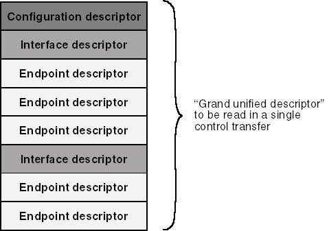
Figure 11-12. Structure of a configuration descriptor.
You must read the entire variable-length structure into a contiguous area of memory because
the hardware won't allow you to directly access the interface and endpoint descriptors.
Unfortunately, you don't initially know how long the combined structure is. The following
fragment of code shows how you can use two URBs to read a configuration descriptor:
ULONG iconfig = 1;
URB urb;
USB_CONFIGURATION_DESCRIPTOR tcd;
UsbBuildGetDescriptorRequest(&urb,
  sizeof(_URB_CONTROL_DESCRIPTOR_REQUEST),
  USB_CONFIGURATION_DESCRIPTOR_TYPE,
  iconfig, 0, &tcd, NULL, sizeof(tcd), NULL);
SendAwaitUrb(fdo, &urb);
ULONG size = tcd.wTotalLength;
PUSB_CONFIGURATION_DESCRIPTOR pcd =
  (PUSB_CONFIGURATION_DESCRIPTOR) ExAllocatePool(
  NonPagedPool, size);
UsbBuildGetDescriptorRequest(&urb,
  sizeof(_URB_CONTROL_DESCRIPTOR_REQUEST),
  USB_CONFIGURATION_DESCRIPTOR_TYPE,
  iconfig, 0, pcd, NULL, size, NULL);
SendAwaitUrb(fdo, &urb);
...
ExFreePool(pcd);
|
In this fragment, we issue one URB to read a configuration descriptor—I specified
configuration number 1, which is the first one—into a temporary descriptor area named
tcd. This descriptor contains the length (wTotalLength) of the combined structure
that includes configuration, interface, and endpoint descriptors. We allocate that much memory
and issue a second URB to read the entire descriptor. At the end of the process, the pcd
variable points to the whole shebang. (Don't leave out the error checking as I just
did—see the code samples on the companion disc for examples of how to handle the many
errors that might arise in this short sequence.)
If your device has a single configuration, go ahead to the next step using the descriptor
set you've just read. Otherwise, you'll need to enumerate the configurations (that is,
step the iconfig variable from 1 to the bNumConfigurations value in the device
descriptor) and apply some sort of algorithm to pick between them.
Selecting the Configuration
You eventually have to select a configuration by sending a series of control commands to the
device to set the configuration and enable the desired interfaces. We'll be using a
function named USBD_CreateConfigurationRequestEx to create the URB for this series of
commands. One of its arguments is an array of pointers to descriptors for the interfaces you
intend to enable. Your next step in configuration after settling on the configuration you want
to use, therefore, is to prepare this array.
Recall that when we read the configuration descriptor, we also read all of its interface
descriptors into adjacent memory. This memory therefore contains a series of descriptors: a
configuration descriptor, an interface descriptor followed by all of its endpoints, another
interface descriptor followed by all of its endpoints, and so on. One way of choosing
interfaces is to parse through this collection of descriptors and remember the addresses of the
interface descriptors you're interested in. The bus driver provides a routine named
USBD_ParseConfigurationDescriptorEx to simplify that task:
PUSB_INTERFACE_DESCRIPTOR pid;
pid = USBD_ParseConfigurationDescriptorEx(pcd, StartPosition,
  InterfaceNumber, AlternateSetting, InterfaceClass,
  InterfaceSubclass, InterfaceProtocol);
|
In this function, pcd is the address of the grand unified configuration descriptor.
StartPosition is either the address of the configuration descriptor (the first time you
make this call) or the address of a descriptor at which you want to begin searching. The
remaining parameters specify criteria for a descriptor search. The value -1 indicates that you
don't want the corresponding criterion to be employed in the search. You can look for the
next interface descriptor that has zero or more of these attributes:
- The given InterfaceNumber
- The given AlternateSetting index
- The given InterfaceClass index
- The given InterfaceSubclass index
- The given InterfaceProtocol index
When USBD_ParseConfigurationDescriptorEx returns an interface descriptor to you, you save it
as the InterfaceDescriptor member of an element in an array of USBD_INTERFACE_LIST_ENTRY
structures, and then you advance past the interface descriptor so that you can parse the next
one. The array of interface list entries will be one of the parameters to the eventual call to
USBD_CreateConfigurationRequestEx, so I need to say a little more about it. Each entry in the
array is an instance of the following structure:
typedef struct _USBD_INTERFACE_LIST_ENTRY {
    PUSB_INTERFACE_DESCRIPTOR InterfaceDescriptor;
    PUSBD_INTERFACE_INFORMATION Interface;
} USBD_INTERFACE_LIST_ENTRY, *PUSBD_INTERFACE_LIST_ENTRY;
|
When you initialize an entry in the array, you set the InterfaceDescriptor member
equal to the address of an interface descriptor that you want to enable and you set the
Interface member to NULL. You define one entry for each interface, and then you add an
additional entry whose InterfaceDescriptor is NULL to mark the end. For example, in my USB42
sample, I know in advance that only one interface exists, so I use the following code to create
the interface list:
PUSB_INTERFACE_DESCRIPTOR pid =
  USBD_ParseConfigurationDescriptorEx(pcd, pcd, -1, -1, -1, -1, -1);
USBD_INTERFACE_LIST_ENTRY interfaces[2] = {
  {pid, NULL},
  {NULL, NULL},
  };
|
That is, I parse the configuration descriptor to locate the first (and only) interface
descriptor. Then I define a 2-element array to describe that one interface.
If you need to enable more than one interface because you're providing your own
multifunction device support, you'll repeat the parsing call in a loop. For example:
1


2
3
|
  ULONG size = (pcd->bNumInterfaces + 1) *
    sizeof(USBD_INTERFACE_LIST_ENTRY);
  PUSBD_INTERFACE_LIST_ENTRY interfaces =
    (PUSBD_INTERFACE_LIST_ENTRY) ExAllocatePool(NonPagedPool, size);
  RtlZeroMemory(interfaces, size);
  ULONG i = 0;
  PUSB_INTERFACE_DESCRIPTOR pid = (PUSB_INTERFACE_DESCRIPTOR) pcd;
  while ((pid = USBD_ParseConfigurationDescriptorEx(pcd, pid, ...)))
    interfaces[i++].InterfaceDescriptor = pid++;
|
- We first allocate memory to hold as many interface list entries as there are
interfaces in this configuration, plus one. We zero the entire array. Wherever we leave off in
filling the array during the subsequent loop, the next entry will be NULL to mark the end of
the array.
- The parsing call includes whatever criteria are relevant to your device. In the
first iteration of the loop, pid points to the configuration descriptor. In later
iterations, it points just past the interface descriptor returned by the preceding call.
- Here, we initialize the pointer to an interface descriptor. The postincrement of
i causes the next iteration to initialize the next element in the array. The
postincrement of pid advances past the current interface descriptor so that the next
iteration parses the next interface. (If you call USBD_ParseConfigurationDescriptorEx with the second argument pointing to an interface
descriptor that meets your criteria, you'll get back a pointer to that same descriptor. If
you don't advance past that descriptor before making the next call, you're doomed to
repeat the loop forever.)
The next step in the configuration process is to create a URB that we'll
submit—soon, I promise—to configure the device:
PURB selurb = USBD_CreateConfigurationRequestEx(pcd, interfaces);
|
In addition to creating a URB (to which selurb points at this moment), USBD_CreateConfigurationRequestEx also initializes the Interface members of your USBD_INTERFACE_LIST entries to point to USBD_INTERFACE_INFORMATION structures. These information
structures are physically located in the same memory block as the URB and will, therefore, be
released back to the heap when you eventually call ExFreePool to return the URB. An
interface information structure has the following declaration:
typedef struct _USBD_INTERFACE_INFORMATION {
  USHORT Length;
  UCHAR InterfaceNumber;
  UCHAR AlternateSetting;
  UCHAR Class;
  UCHAR SubClass;
  UCHAR Protocol;
  UCHAR Reserved;
  USBD_INTERFACE_HANDLE InterfaceHandle;
  ULONG NumberOfPipes;
  USBD_PIPE_INFORMATION Pipes[1];
  } USBD_INTERFACE_INFORMATION, *PUSBD_INTERFACE_INFORMATION;
|
The array of pipe information structures is what we're really interested in at this
point, since the other fields of the structure will be filled in by USBD when we submit this
URB. Each of them looks like this:
typedef struct _USBD_PIPE_INFORMATION {
  USHORT MaximumPacketSize;
  UCHAR EndpointAddress;
  UCHAR Interval;
  USBD_PIPE_TYPE PipeType;
  USBD_PIPE_HANDLE PipeHandle;
  ULONG MaximumTransferSize;
  ULONG PipeFlags;
  } USBD_PIPE_INFORMATION, *PUSBD_PIPE_INFORMATION;
|
So, we have an array of USBD_INTERFACE_LIST entries, each of which points to a
USBD_INTERFACE_INFORMATION structure that contains an array of USBD_
PIPE_INFORMATION structures. Our immediate task is to fill in the MaximumTransferSize
member of each of those pipe information structures if we don't want to accept the default
value chosen by USBD. The default value is USBD_DEFAULT_MAXIMUM_TRANSFER_SIZE, which was equal to PAGE_SIZE in the DDK I was using at the time I wrote
this book. The value we specify isn't directly related either to the maximum transfer size
for the endpoint (which governs how many bytes can be moved in a single bus transaction) or to
the amount of data the endpoint can absorb in a series of transactions (which is determined by
the amount of memory available on the device). Instead, it represents the largest amount of
data we will attempt to move with a single URB. This can be less than the largest amount of
data that an application might send to the device or receive from the device, in which case our
driver must be prepared to break application requests into pieces no bigger than this maximum
size. I'll discuss how that task can be accomplished later in "Managing Bulk Transfer
Pipes."
The reason that we have to supply a maximum transfer size is rooted in the scheduling algorithm
that the host controller drivers use to divide URB requests into transactions within bus
frames. If we send a large amount of data, it's possible for our data to hog a frame to the
exclusion of other devices. We therefore want to moderate our demands on the bus by specifying
a reasonable maximum size for the URBs that we'll send at once.
The code needed to initialize the pipe information structures is something like this:
for (ULONG ii = 0; ii < <number of interfaces>; ++ii)
  {
  PUSBD_INTERFACE_INFORMATION pii = interfaces[ii].Interface;
  for (ULONG ip = 0; ip < pii->NumberOfPipes; ++ip)
    pii->Pipes[ip].MaximumTransferSize = <some constant>;
  }
|
NOTE
The USBD_CreateConfigurationRequestEx function initializes the
MaximumTransferSize member of each pipe information structure to USBD_
DEFAULT_MAXIMUM_TRANSFER_SIZE and the PipeFlags member to 0. Bear this in mind when you look at
older driver samples and when you write your own driver.
Once you've initialized the pipe information structures, you're finally ready to
submit the configuration URB:
SendAwaitUrb(fdo, selurb);
|
Finding the Handles
Successful completion of the select configuration URB leaves behind various handle values
that you should record for later use:
- The UrbSelectConfiguration.ConfigurationHandle member of the URB is a handle for
the configuration.
- The InterfaceHandle member of each USBD_INTERFACE_INFORMATION structure contains a
handle for the interface.
- Each of the USBD_PIPE_INFORMATION structures has a PipeHandle for the pipe ending
in the corresponding endpoint.
For example, the USB42 sample records two handle values (in the device extension):
typedef struct _DEVICE_EXTENSION {
  ...
  USBD_CONFIGURATION_HANDLE hconfig;
  USBD_PIPE_HANDLE hpipe;
  } DEVICE_EXTENSION, *PDEVICE_EXTENSION;

pdx->hconfig = selurb->UrbSelectConfiguration.ConfigurationHandle;
pdx->hpipe = interfaces[0].Interface->Pipes[0].PipeHandle;
ExFreePool(selurb);
|
At this point in the program, the select configuration URB is no longer needed and can be
discarded.
Shutting Down the Device
When your driver receives an IRP_MN_STOP_DEVICE request, you should place the device into
its unconfigured state by creating and submitting a select configuration request with a NULL
configuration pointer:
URB urb;
UsbBuildSelectConfigurationRequest(&urb,
  sizeof(_URB_SELECT_CONFIGURATION), NULL);
SendAwaitUrb(fdo, &urb);
|
Managing Bulk Transfer Pipes
The companion disc has two sample programs that illustrate bulk transfers. The first and
simplest is named USB42. It has an input bulk endpoint that delivers back the constant value 42
each time you read it. (I call this the Answer device because the number 42 is Douglas
Adams's answer to the Ultimate Question of Life, the Universe and Everything in The
Hitchhiker's Guide to the Galaxy. Most readers probably already knew that, actually,
given our common affinity for science fiction.) The code to do the reading is as follows:
URB urb;
UsbBuildInterruptOrBulkTransferRequest(&urb,
  sizeof(_URB_BULK_OR_INTERRUPT_TRANSFER),
  pdx->hpipe, Irp->AssociatedIrp.SystemBuffer, NULL, cbout,
  USBD_TRANSFER_DIRECTION_IN | USBD_SHORT_TRANSFER_OK, NULL);
status = SendAwaitUrb(fdo, &urb);
|
This code runs in the context of the handler for a DeviceIoControl call that uses the
buffered method for data access, so the SystemBuffer field of the IRP points to the
place to which data should be delivered. The cbout variable is the size of the data
buffer we're trying to fill.
There's not much to explain about this request. You indicate with a flag whether you're
reading (USBD_TRANSFER_DIRECTION_IN) or writing (no such flag) the endpoint. You can optionally
indicate with another flag bit (USBD_SHORT_
TRANSFER_OK) whether you're willing to tolerate having the device provide or consume less
data than the maximum for the endpoint. The pipe handle is something you capture at
IRP_MN_START_DEVICE time in the manner already illustrated.
The LOOPBACK sample is considerably more complicated than USB42. The device it manages has two
bulk transfer endpoints, one for input and another for output. You can feed up to 16,384 bytes
into the output pipe, and you can retrieve what you put in from the input pipe. The driver
itself uses standard IRP_MJ_READ and IRP_MJ_WRITE requests for data movement. Handling read and
write requests is so similar that the dispatch routines simply delegate these requests to a
helper function named ReadWrite:
NTSTATUS DispatchRead(PDEVICE_OBJECT fdo, PIRP Irp)
  {
  return ReadWrite(fdo, Irp, TRUE);
  }

NTSTATUS DispatchWrite(PDEVICE_OBJECT fdo, PIRP Irp)
  {
  return ReadWrite(fdo, Irp, FALSE);
  }

NTSTATUS ReadWrite(PDEVICE_OBJECT fdo, PIRP Irp, BOOLEAN read)
  {
  PDEVICE_EXTENSION pdx = (PDEVICE_EXTENSION) fdo->DeviceExtension;
  NTSTATUS status = IoAcquireRemoveLock(&pdx->RemoveLock, Irp);
  if (!NT_SUCCESS(status))
    return CompleteRequest(Irp, status, 0);
  ...
  IoMarkIrpPending(Irp);
  IoSetCompletionRoutine(Irp, (PIO_COMPLETION_ROUTINE)
    OnReadWriteComplete, ...);
  IoCallDriver(...);
  return STATUS_PENDING;
  }
|
In summary, ReadWrite acquires the remove lock, creates a URB to do a bulk transfer,
installs a completion routine, and submits the URB to the bus driver. The function deals with
the two complications that make this sample more informative than USB42: the I/O operation
might result in an error, and the request might need to be broken up to be handled in
stages.
LOOPBACK's overall strategy for submitting requests to the bus driver is to change the
personality of the read or write IRP into an IRP_MJ_INTERNAL_DEVICE_CONTROL containing a URB and send this altered IRP down the stack. To us and every
driver above us, the IRP looks like an IRP_MJ_READ or IRP_MJ_WRITE because one of those two
values will be in the MajorFunction field of the corresponding stack location. To the
drivers below us, however, the IRP looks like an internal control request. The completion
routine will resubmit this same IRP to perform the second and subsequent stages of a large
transfer. Both features of this strategy are perfectly legal but will probably seem novel if
you're seeing them for the first time. Without the error checking that's in the real
LOOPBACK sample, here's ReadWrite and its associated completion routine in all their
glory:
1


2


3

4


5


6


7


8


9

10


11


12


13
|
struct _RWCONTEXT : public _URB
  {
  ULONG_PTR va;
  ULONG length;
  PMDL mdl;
  ULONG numxfer;
  };

NTSTATUS ReadWrite(PDEVICE_OBJECT fdo, PIRP Irp, BOOLEAN read)
  {
  PDEVICE_EXTENSION pdx = (PDEVICE_EXTENSION) fdo->DeviceExtension;
  NTSTATUS status = IoAcquireRemoveLock(&pdx->RemoveLock, Irp);
  if (!NT_SUCCESS(status))
    return CompleteRequest(Irp, status, 0);
  USBD_PIPE_HANDLE hpipe = read ? pdx->hinpipe : pdx->houtpipe;

  LONG haderr;
  if (read)
    haderr = InterlockedExchange(&pdx->inerror, 0);
  else
    haderr = InterlockedExchange(&pdx->outerror, 0);
  if (haderr && !NT_SUCCESS(ResetPipe(fdo, hpipe)))
    ResetDevice(fdo);

  PRWCONTEXT ctx = (PRWCONTEXT) ExAllocatePool(NonPagedPool,
    sizeof(RWCONTEXT));
  RtlZeroMemory(ctx, sizeof(RWCONTEXT));

  ULONG length = Irp->MdlAddress
    ? MmGetMdlByteCount(Irp->MdlAddress) : 0;
  if (!length)
    {
    IoReleaseRemoveLock(&pdx->RemoveLock, Irp);
    return CompleteRequest(Irp, STATUS_SUCCESS, 0);
    }
  ULONG_PTR va = (ULONG_PTR) MmGetMdlVirtualAddress(Irp->MdlAddress);

  ULONG urbflags = (read ? USBD_TRANSFER_DIRECTION_IN
                         : USBD_TRANSFER_DIRECTION_OUT);

  ULONG seglen = length;
  if (seglen > MAXTRANSFER)
    seglen = (ULONG_PTR) PAGE_ALIGN(va) + PAGE_SIZE - va;

  PMDL mdl = IoAllocateMdl((PVOID) va, PAGE_SIZE, FALSE, FALSE, NULL);
  IoBuildPartialMdl(Irp->MdlAddress, mdl, (PVOID) va, seglen);

  UsbBuildInterruptOrBulkTransferRequest(ctx,
    sizeof(_URB_BULK_OR_INTERRUPT_TRANSFER),
    hpipe, NULL, mdl, seglen, urbflags, NULL);

  ctx->va = va + seglen;
  ctx->length = length - seglen;
  ctx->mdl = mdl;
  ctx->numxfer = 0;

  PIO_STACK_LOCATION stack = IoGetNextIrpStackLocation(Irp);
  stack->MajorFunction = IRP_MJ_INTERNAL_DEVICE_CONTROL;
  stack->Parameters.Others.Argument1 = (PVOID) (PURB) ctx;
  stack->Parameters.DeviceIoControl.IoControlCode =
    IOCTL_INTERNAL_USB_SUBMIT_URB;

  IoSetCompletionRoutine(Irp, (PIO_COMPLETION_ROUTINE)
    OnReadWriteComplete, (PVOID) ctx, TRUE, TRUE, TRUE);

  IoMarkIrpPending(Irp);
  status = IoCallDriver(pdx->LowerDeviceObject, Irp);
  return STATUS_PENDING;
  }

NTSTATUS OnReadWriteComplete(PDEVICE_OBJECT fdo, PIRP Irp, PRWCONTEXT ctx)
  {
  PDEVICE_EXTENSION pdx = (PDEVICE_EXTENSION) fdo->DeviceExtension;
  BOOLEAN read =
    (ctx->UrbBulkOrInterruptTransfer.TransferFlags &
    USBD_TRANSFER_DIRECTION_IN) != 0;
  ctx->numxfer +=
    ctx->UrbBulkOrInterruptTransfer.TransferBufferLength;

  NTSTATUS status = Irp->IoStatus.Status;
  if (NT_SUCCESS(status) && ctx->length)
    {
    ULONG seglen = ctx->length;
    if (seglen > MAXTRANSFER)
      seglen = (ULONG_PTR) PAGE_ALIGN(ctx->va) +
        PAGE_SIZE - ctx->va;

    IoBuildPartialMdl(Irp->MdlAddress, ctx->mdl,
      (PVOID) ctx->va, seglen);

    ctx->UrbBulkOrInterruptTransfer.TransferBufferLength = seglen;

	PIO_STACK_LOCATION stack = IoGetNextIrpStackLocation(Irp);
    stack->MajorFunction = IRP_MJ_INTERNAL_DEVICE_CONTROL;
    stack->Parameters.Others.Argument1 = (PVOID) (PURB) ctx;
    stack->Parameters.DeviceIoControl.IoControlCode =
      IOCTL_INTERNAL_USB_SUBMIT_URB;
    IoSetCompletionRoutine(Irp, (PIO_COMPLETION_ROUTINE)
      OnReadWriteComplete, (PVOID) ctx, TRUE, TRUE, TRUE);

    ctx->va += seglen;
    ctx->length -= seglen;

    IoCallDriver(pdx->LowerDeviceObject, Irp);
    return STATUS_MORE_PROCESSING_REQUIRED;
    }

  if (NT_SUCCESS(status))
    Irp->IoStatus.Information = ctx->numxfer;
  else
    {
    if (read)
      InterlockedIncrement(&pdx->inerror);
    else
      InterlockedIncrement(&pdx->outerror);
    }

  ExFreePool(ctx->mdl);
  ExFreePool(ctx);
  IoReleaseRemoveLock(&pdx->RemoveLock, Irp);

  return status;
  }
|
- ReadWrite needs to create a URB that it will share with
OnReadWriteComplete, and it needs to provide some additional context information to keep
track of the ongoing progress of the operation. This RWCONTEXT structure encompasses both
purposes. (Deriving one structure from another as shown here is a C++ stratagem for declaring a
structure that begins with the members of the base structure.) In addition to the URB, this
structure includes va, the virtual address of the current portion of the user-mode
buffer; length, the residual count for this operation; mdl, a partial memory
descriptor list describing the current segment of the transfer; and numxfer, the
cumulative number of bytes transferred.
- We acquire the remove lock here. The balancing call to IoReleaseRemoveLock
occurs in the completion routine.
- This is one of a few places where ReadWrite needs to distinguish between read and
write requests. Here, we're obtaining the handle of the pipe through which we'll move
data.
- Either the input or the output pipe might have had an error the last time we
tried to use it, in which case either inerror or outerror will be set in the
device extension. Before launching a new operation, we try to reset the pipe that had the
error. If that doesn't work, we reset the entire device. I'll explain the
ResetPipe and ResetDevice helper functions in the next section.
- This driver declared itself as using the DO_DIRECT_IO buffering method at
AddDevice time, so the IRP has a pointer to a memory descriptor list describing the (locked)
pages containing the user-mode buffer. It's customary to obtain the transfer length from
the MDL, as shown here, rather than from the stack location.
- We'll be performing the operation in blocks no bigger than a page. The choice
of PAGE_SIZE as a maximum transfer size was a design choice, and you might pick a different
value as previously described. To gain whatever benefits might flow from processing a
page-aligned buffer, I also decided to make the first transfer short, if necessary, so that
later transfers would be page-aligned.
- We'll be using a partial memory descriptor list for each segment of the
transfer. We need an MDL that has the capacity to describe the largest number of pages
we'll transfer in a single segment. This number is either one or two, depending on the
alignment of the buffer. After allocating the MDL, we call IoBuildPartialMdl to map the
initial segment.
- We're ready at this point to build and submit a URB for the first segment of
the read or write. The key task here is our initialization of the next driver's stack entry
to describe an internal control operation instead of a read or write. The main advantage of
doing this is that we don't need extra, fairly involved logic to handle cancellation of a
subsidiary IRP when the main read/write IRP gets cancelled.
- When one stage in the transfer completes successfully, the bus driver calls
IoCompleteRequest and our completion routine gains control. If the request isn't
finished yet, we'll resubmit the URB with a new buffer address and length. Otherwise,
we'll allow the completion process to run its course. Don't forget that the IRP
we're dealing with originally came to us with a major function code of IRP_MJ_READ or
IRP_MJ_WRITE.
- Here we set up the partial MDL for the next segment of the transfer. The
user-mode virtual address is pretty useless per se because this completion routine executes in
an arbitrary thread context. IoBuildPartialMdl is mapping a subset of a master MDL
that's already been probed and locked, however. Since it merely copies physical page
numbers from the master MDL, it doesn't depend on executing in any particular memory
context.
- Here we set up the URB and I/O stack for the next stage. The only field in the
URB that requires change is the byte count. The URB's MDL pointer, flags, and so on, are as
ReadWrite left them. (The MDL itself changed, but its location in memory didn't.) We need
to completely reinitialize the next stack location, however, because IoCompleteRequest set most
of it to 0.
- We reissue this IRP to the bus driver and return the status code STATUS_MORE_PROCESSING_REQUIRED to halt the completion process inside IoCompleteRequest. When this
new stage finishes, this completion routine will regain control.
- Beginning here we handle the final completion of the read/write request. We set
the IoStatus.Information field to be the total number of bytes we've successfully
transferred and clean up the memory we allocated in ReadWrite. We also release the remove lock
to balance the acquisition that ReadWrite did.
You might notice that the completion routine in this sample doesn't contain the standard
boilerplate code to conditionally call IoMarkIrpPending. That's not necessary in
this case because we made that call in ReadWrite.
You'll also notice that when the completion routine calls IoCallDriver to resubmit
the URB, it then unconditionally returns STATUS_MORE_PROCESSING_
REQUIRED. There's an important but subtle reason for this behavior. If the bus driver
accepts the new URB normally, it will return STATUS_PENDING to us. (This is just how USBD
works—it's not a general characteristic of bus drivers.) In this case, we certainly
should return STATUS_MORE_PROCESSING_REQUIRED because we want IoCompleteRequest to stop
processing the IRP for the time being. The bus driver will complete it again later. If the bus
driver were to fail the new submission, however, or if it were for some reason to complete it
in the dispatch routine, it will have called IoCompleteRequest before returning. We've
already processed that completion event in a recursive call! We shouldn't, therefore,
do anything more with this IRP or allow the initial invocation of IoCompleteRequest to do
anything with it either. Returning STATUS_MORE_PROCESSING_REQUIRED is always the right thing to
do here.
Error Recovery
I can't say much of a general nature about recovering from errors in USB operations.
When you send or receive data to a bulk transfer endpoint, the bus and bus driver take care of
retrying garbled transmissions. Consequently, if your URB appears to complete successfully, you
can be confident that the data you intended to transfer has in fact been transferred correctly.
When an error occurs, however, your driver needs to attempt some sort of recovery. The first
line of defense is generally to unstall the endpoint with which you've been trying to
communicate so that you can try again. Here's a helper routine named ResetPipe that
will do that:
NTSTATUS ResetPipe(PDEVICE_OBJECT fdo, USBD_PIPE_HANDLE hpipe)
  {
  URB urb;
  urb.UrbHeader.Length = (USHORT) sizeof(_URB_PIPE_REQUEST);
  urb.UrbHeader.Function = URB_FUNCTION_RESET_PIPE;
  urb.UrbPipeRequest.PipeHandle = hpipe;

  NTSTATUS status = SendAwaitUrb(fdo, &urb);
  return status;
  }
|
As you can see, all that's required is to submit a URB with the RESET_PIPE function
code. Since this helper routine indirectly waits for the URB to complete, you must be running
at PASSIVE_LEVEL to call it. What this URB does, in USB terms, is clear the ENDPOINT_HALT
feature. If the endpoint was stalled, it then becomes ready for the next transaction.
If you're unable to reset the pipe, you can then try to reset the entire device by using
this ResetDevice function:
VOID ResetDevice(PDEVICE_OBJECT fdo)
  {
  PDEVICE_EXTENSION pdx = (PDEVICE_EXTENSION) fdo->DeviceExtension;

  KEVENT event;
  KeInitializeEvent(&event, NotificationEvent, FALSE);
  IO_STATUS_BLOCK iostatus;

  PIRP Irp = IoBuildDeviceIoControlRequest
    (IOCTL_INTERNAL_USB_RESET_PORT, pdx->LowerDeviceObject,
    NULL, 0, NULL, 0, TRUE, &event, &iostatus);
  if (!Irp)
    return;

  NTSTATUS status = (IoCallDriver(pdx->LowerDeviceObject, Irp);
  if (status == STATUS_PENDING)
    KeWaitForSingleObject(&event, Executive, KernelMode,
      FALSE, NULL);
  }
|
The port-reset command causes the hub driver to reinitialize the device while preserving the
existing configuration. This process might fail somewhere along the way, in which case the
command will complete with an error status. If the device turns out to be missing, for example,
the hub driver fails the request with STATUS_UNSUCCESSFUL.
Managing Interrupt Pipes
From the device side of the bus, an interrupt pipe is practically identical to a bulk
transfer pipe. The only important difference from that perspective is that the host will be
polling an interrupt endpoint with some guaranteed frequency. The device will respond with NAK
except at instants when it will present an interrupt to the host. To report an interrupt event,
the device ACKs the host after providing whatever morsel of data is supposed to accompany the
interrupt.
From the driver's perspective, managing an interrupt pipe is quite a bit more complicated
than managing a bulk pipe. When the driver needs to read or write data to a bulk pipe, it just
creates an appropriate URB and sends it to the bus driver. But for an interrupt pipe to serve
its intended purpose of notifying the host of interesting hardware events, the driver basically
needs to keep a read request outstanding at all times. I don't recommend using a
system-polling thread in this case because power management greatly complicates the management
of the separate thread. The best way to keep a read request active is to use the same idea I
showed you in LOOPBACK, where we have a completion routine that keeps recycling a URB.
The USBINT sample illustrates how to manage an interrupt pipe with a URB that's always
active. I wrote a few helper routines to assist in the job. I won't describe all of these
functions in detail; please refer to the READWRITE.CPP file with the USBINT sample on the
companion disc.
CreateInterruptUrb CreateInterruptUrb creates the URB and an associated IRP. The device
extension has fields named PollingUrb and PollingIrp that point to these two
structures. We call this function during our processing of IRP_MN_START_DEVICE.
DeleteInterruptUrb DeleteInterruptUrb is the counterpart of CreateInterruptUrb. Whenever
we're shutting the device down, we call this function to release the IRP and URB memory
blocks.
StartInterruptUrb StartInterruptUrb launches a URB to poll the device's interrupt endpoint.
We call this function whenever we activate the device, which we do when we open the first
handle after a period in which no handles were open. (We also power the device on at the same
time. We can't have a URB outstanding when the device is powered down, but we want one
outstanding when the device is powered up in order to service an application.)
OnInterrupt OnInterrupt is a standard I/O completion routine that functions as an interrupt
routine for the device. It looks like this:
1
2


3
|
NTSTATUS OnInterrupt(PDEVICE_OBJECT junk, PIRP Irp,
  PDEVICE_EXTENSION pdx)
  {
  if (NT_SUCCESS(Irp->IoStatus.Status))
    {
    KdPrint(("USBINT - Interrupt!\n"));
    StartInterruptUrb(pdx->DeviceObject);
    }

  return STATUS_MORE_PROCESSING_REQUIRED;
  }
|
- This is where you would do whatever interrupt processing is required by your
device. In the USBINT sample, there's code at this point to increment a count of pending
interrupts or complete a pending IOCTL that an application is using as a means of knowing when
interrupts occur.
- Here, we initiate another poll for an interrupt using the same URB.
- We return STATUS_MORE_PROCESSING_required because we don't want
IoCompleteRequest to do anything else with the IRP.
Control Requests
If you refer back to Table 11-2, you'll notice that there are 11 standard
types of control requests. You and I will never explicitly issue SET_ADDRESS requests. The bus
driver does that when a new device initially comes on line; by the time we ever get control in
a WDM driver, the bus driver has assigned an address to the device and read the device
descriptor to learn that we're the device driver. I've already discussed how to
create the URBs that cause the bus driver to send control requests for getting descriptors or
for setting a configuration or interface in the "Initiating Requests" and
"Configuration" sections. In this section, I'll fill in the blanks related to the
remaining kinds of control transactions.
Controlling Features
If we want to set or clear a feature of a device, an interface, or an endpoint, we submit a
feature URB. For example, the following code (which appears in the FEATURE sample driver on the
companion disc) sets a vendor-defined interface feature:
URB urb;
UsbBuildFeatureRequest(&urb,
  URB_FUNCTION_SET_FEATURE_TO_INTERFACE,
  FEATURE_LED_DISPLAY, 1, NULL);
status = SendAwaitUrb(fdo, &urb);
|
The second argument to UsbBuildFeatureRequest indicates whether we want to set or
clear a feature belonging to the device, an interface, an endpoint, or another vendor-specific
entity on the device. This parameter takes eight possible values, and you could guess without
me telling you that they're formed according to the following formula:
URB_FUNCTION_ [SET | CLEAR] _FEATURE_TO_
  [DEVICE | INTERFACE | ENDPOINT | OTHER]
|
The third argument to UsbBuildFeatureRequest identifies the feature in question. In the
FEATURE sample, I invented a feature called FEATURE_LED_DISPLAY. The fourth argument identifies
a particular entity of whatever type is being addressed. In this example, I wanted to address
interface 1, so I coded 1.
USB defines two standard features that you might be tempted to control yourself using a
feature URB: the remote wake-up feature and the endpoint stall feature. You don't, however,
need to set or clear these features yourself because the bus driver does so automatically. When
you issue an IRP_MN_WAIT_WAKE request—see Chapter 8, "Power Management"—the
bus driver ensures that the device's configuration allows for remote wake-up, and it also
automatically enables the remote wake-up feature for the device. The bus driver issues a clear
feature request to unstall a device when you issue a RESET_PIPE URB.
Determining Status
If you want to obtain the current status of the device, an interface, or an endpoint, you
formulate a get status URB. For example:
URB urb;
USHORT epstatus;
UsbBuildGetStatusRequest(&urb, URB_FUNCTION_GET_STATUS_FROM_ENDPOINT,
  <index>, &epstatus, NULL, NULL);
SendAwaitUrb(fdo, &urb);
|
You can use four different URB functions in a get status request, and they allow you to
retrieve the current status mask for the device as a whole, for a specified interface, for a
specified endpoint, or for a vendor-specific entity. See Table 11-8.
The status mask for a device indicates whether the device is self-powered and whether or not
its remote wake-up feature is enabled. See Figure 11-13. The mask for an endpoint indicates
whether or not the endpoint is currently stalled. See Figure 11-14. USB now defines
interface-level status bits related to power management. Refer to the "USB Feature
Specification: Interface Power Management" document on line at the USB Web site, which at
press time was available at http://www.usb.org/developers/devclass.html. USB should
never prescribe vendor-specific status bits since they're, by definition, up to vendors to
specify.
Table 11-8. URB function codes used for getting status.
| Operation Code |
Retrieve Status From… |
| URB_FUNCTION_GET_STATUS_FROM_DEVICE |
Device as a whole |
| URB_FUNCTION_GET_STATUS_FROM_INTERFACE |
Specified interface |
| URB_FUNCTION_GET_STATUS_FROM_ENDPOINT |
Specified endpoint |
| URB_FUNCTION_GET_STATUS_FROM_OTHER |
Vendor-specific object |
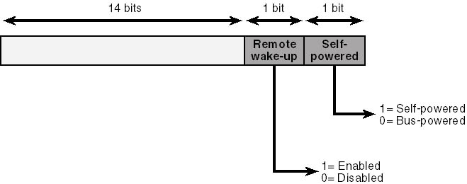
Figure 11-13. Bits in device status.
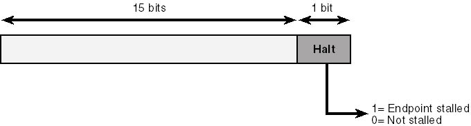
Figure 11-14. Bits in endpoint status.
Managing Isochronous Pipes
The purpose of an isochronous pipe is to allow the host and the device to exchange
time-critical data with guaranteed regularity. The bus driver will devote up to 90 percent of
the bus bandwidth to isochronous and interrupt transfers. What this means is that every 1-ms
frame will include reserved time slots long enough to accommodate maximum-sized transfers to or
from each of the isochronous and interrupt endpoints that are currently active. Figure 11-15
illustrates this concept for three different devices. Devices A and B each have an isochronous
endpoint, for which a fixed and relatively large amount of time is reserved in every frame.
Device C has an interrupt endpoint whose polling frequency is once every two frames; it has a
reservation for a small portion of every second frame. During frames that don't include a
poll of Device C's interrupt endpoint, additional bandwidth would be available, perhaps for
bulk transfers or other purposes.
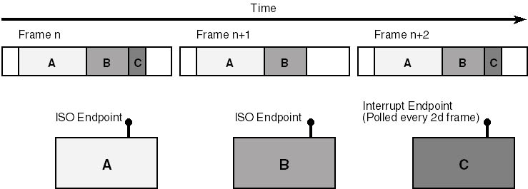
Figure 11-15. Allocation of bandwidth to isochronous and interrupt endpoints.
Reserving Bandwidth
The bus driver reserves bandwidth for you when you enable an interface by examining the
endpoint descriptors that are part of the interface. Reserving bandwidth is just like buying a
theater ticket, though: you don't get a refund if you don't use the space.
Consequently, it's important to enable an interface that contains an isochronous endpoint
only when you'll be using the bandwidth you thereby reserve, and it's important that
the endpoint's declared maximum transfer size be approximately the amount you intend to
use. Normally, a device with isochronous capability has a default interface that doesn't
have any isochronous or interrupt endpoints. When you know you're about to access that
capability, you enable an alternate setting of the same interface that does have
the isochronous or interrupt endpoints.
An example will clarify the mechanics of reserving bandwidth. The USBISO sample on the
companion disc has an interface with a default and an alternate setting. The default setting
has no endpoints. The alternate setting has an isochronous endpoint with a maximum transfer
size of 256 bytes. See Figure 11-16.
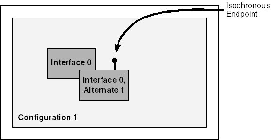
Figure 11-16. Descriptor structure for the USBISO device.
At StartDevice time, we select a configuration based on the default interface. Since the
default interface doesn't have an isochronous or interrupt endpoint in it, we don't
reserve any bandwidth just yet. When someone opens a handle to the device, however, we invoke
the following SelectAlternateInterface helper function to switch to the alternate
setting for our interface. (Again, I've omitted the error checking.)
1


2


3
4


5
6

7
|
NTSTATUS SelectAlternateInterface(PDEVICE_OBJECT fdo)
  {
  PDEVICE_EXTENSION pdx = (PDEVICE_EXTENSION) fdo->DeviceExtension;
  PUSB_INTERFACE_DESCRIPTOR pid =
    USBD_ParseConfigurationDescriptorEx(pdx->pcd, pdx->pcd,
      0, 1, -1, -1, -1);
  ULONG npipes = pid->bNumEndpoints;
  ULONG size = GET_SELECT_INTERFACE_REQUEST_SIZE(npipes);
  PURB urb = (PURB) ExAllocatePool(NonPagedPool, size);
  RtlZeroMemory(urb, size);
  UsbBuildSelectInterfaceRequest(urb, size, pdx->hconfig, 0, 1);
  urb->UrbSelectInterface.Interface.Length =
    GET_USBD_INTERFACE_SIZE(npipes);
  urb->UrbSelectInterface.Interface.Pipes[0].MaximumTransferSize =
    PAGE_SIZE;
  NTSTATUS status = SendAwaitUrb(fdo, &urb);
  if (NT_SUCCESS(status))
    {
    pdx->hinpipe =
      urb.UrbSelectInterface.Interface.Pipes[0].PipeHandle;
    status = STATUS_SUCCESS;
    }
  ExFreePool(urb);
  return status;
  }
|
- Before we can allocate space for the URB, we need to know how many pipe
descriptors it will contain. The most common way to find this number is to go back to the grand
unified configuration descriptor and find the descriptor for interface 0, alternate setting 1.
That descriptor contains a count of endpoints, which is the same as the number of pipes that
we're about to open.
- GET_SELECT_INTERFACE_REQUEST_SIZE calculates the number of bytes needed to hold a
select interface request that will open the specified number of pipes. We can then allocate
memory for the URB and initialize it to 0. The real code sample on the companion disc checks to
make sure that the call to ExAllocatePool succeeded, by the way.
- Here, we build a URB to select alternate setting 1 (the last argument) of
interface number 0 (the next-to-last argument).
- We must do these two additional initialization steps to finish setting up the
URB. Failing to set the interface information structure's length earns you a
STATUS_BUFFER_TOO_SMALL failure right away. Failing to set the MaximumTransferSize
fields of the pipe descriptors earns you a STATUS_INVALID_PARAMETER when you try to read or write the pipe.
- When we submit this URB, USBD automatically closes the current setting of this
interface, including all of its endpoints. Then USBD tells the device to enable the alternate
setting, and it creates pipe descriptors for the endpoints that are part of the alternate
setting. If opening the new interface fails for some reason, USBD reopens the previous
interface, and all your previous interface and pipe handles remain valid.
- My SendAwaitUrb helper function simply returns an error if it's unable
to select the one-and-only alternate setting for this interface. I'll have a bit more to
say about how you should handle errors after this numbered list.
- In addition to selecting the new interface at the device level, USBD also creates
an array of pipe descriptors from which we can extract handles for later use.
The select interface call might fail because not enough free bandwidth exists to accommodate
our endpoint. We would find out about the failure by examining the URB status:
if (URB_STATUS(&urb) == USBD_STATUS_NO_BANDWIDTH)
  ...
|
Dealing with lack of bandwidth poses a bit of a problem. The operating system doesn't
currently provide a convenient way for competing drivers to negotiate a fair allocation.
Neither does it provide for any sort of notification that some other driver has failed to
acquire needed bandwidth so that we might give up some of ours. In this state of affairs,
therefore, you have two basic choices. One choice is to provide multiple alternate interface
settings, each of which has a different maximum transfer size for its isochronous endpoint(s).
When you detect an allocation failure, you can try to select progressively less-demanding
settings until you finally succeed.
A savvy end user who's able to launch the Windows 2000 Device Manager applet can display a
property page for the USB host controller—see Figure 11-17—that displays information
about the current allocation of bandwidth. Double-clicking one of the devices listed in the
page brings up the property display for the device in question. A well-crafted page could
perhaps communicate with the associated device driver in order to scale back its demand for
bandwidth. This whole area seems ripe for a more automatic Microsoft-driven solution,
though.
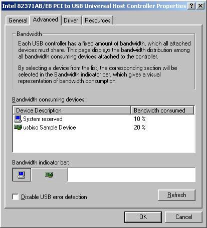
Figure 11-17. A property page for the USB host controller.
Your other choice for handling lack of bandwidth is to allow an IRP to fail in such a way that
an application can alert the end user to the problem. Perhaps the end user can unplug something
so that your device can be accommodated. This is the option I chose in the USBISO sample except
I didn't bother to put code into the test application that would respond to a bandwidth
allocation failure—TEST.EXE will just fail. To adopt this option, you need to know how the
failure shows up back in user mode. If the URB fails with USBD_STATUS_NO_BANDWIDTH, the
NTSTATUS code you get back from the internal control IRP is STATUS_DEVICE_DATA_ERROR, which
isn't very specific. An application call to GetLastError would retrieve ERROR_CRC as the error code. There's no easy way for an application to discover that the real
cause of the error is a lack of bandwidth, unfortunately. If you're interested in diving
down this particular rat hole to reach a conclusion, read the sidebar.
USBISO performs the converse operation of selecting the original default interface when it
receives the IRP_MJ_CLOSE for the last remaining open handle. That operation entails issuing
another select interface URB, but with the value 0 for the alternate interface index.
Initiating a Series of Isochronous Transfers
You can use an isochronous pipe either to read or write data in discrete chunks or to
provide or consume data in a continuous stream. Data streaming is probably the most frequent
occupation for an isochronous pipe, actually. But, in addition to understanding the mechanics
of working with the USB bus driver, you must understand and solve additional problems related
to data buffering, rate matching, and so on, if you want to operate a streaming pipe. The
kernel-streaming component of the operating system deals with all these additional
problems. Unfortunately, we didn't have time to include a chapter on kernel streaming in
this book. I'm therefore going to show you only how to program a discrete transfer over an
isochronous pipe.
To read from or write to an isochronous pipe, you'll of course use a URB with the
appropriate function code. But there are a few wrinkles that you haven't seen yet
associated with creating and submitting the isochronous URB. First, you must be aware of how
the device will break up a transfer into packets. In general, the device is free to
accept or deliver any amount of data less than the endpoint's declared maximum. (Any
leftover bandwidth on the bus simply won't be used.) The packet size the device will use
doesn't have any other necessary relation with the endpoint maximum, with the maximum
amount of data you said you'd transfer in a URB, or with the amount of data the device and
application can exchange in a series of transactions. The firmware for the USBISO device, for
example, works with 16-byte packets even though the isochronous endpoint in question can handle
up to 256 bytes per frame according to its descriptor. You must have a priori knowledge of how
big these packets will be before you construct a URB because the URB must include an array of
descriptors for each packet that will be exchanged and each of these descriptors must indicate
how big the packet will be.
In an impractical simple situation, you could allocate an isochronous URB in the following
way:
ULONG length = MmGetMdlByteCount(Irp->MdlAddress);
ULONG packsize = 16; // a constant in USBISO
ULONG npackets = (length + packsize - 1) / packsize;
ASSERT(npackets <= 255);
ULONG size = GET_ISO_URB_SIZE(npackets);
PURB urb = (PURB) ExAllocatePool(NonPagedPool, size);
RtlZeroMemory(urb, size);
|
The key step in this fragment is the use of the GET_ISO_URB_SIZE macro to calculate
the total size needed for an isochronous URB to transfer a given number of data packets. A
single URB can accommodate a maximum of 255 isochronous packets, by the way, which is why I put
the ASSERT statement into this code. Limiting the application to just 255 packets is not
practical, as I said, so we will do something more complex in the real USBISO sample driver.
For the time being, though, I just want to describe the mechanics of building a single URB for
an isochronous (ISO) transfer.
There being no UsbBuild XxxRequest macro for building an isochronous
URB, we go on to initialize the new URB by hand:
urb->UrbIsochronousTransfer.Hdr.Length = (USHORT) size;
urb->UrbIsochronousTransfer.Hdr.Function =
  URB_FUNCTION_ISOCH_TRANSFER;
urb->UrbIsochronousTransfer.PipeHandle = pdx->hinpipe;
urb->UrbIsochronousTransfer.TransferFlags =
  USBD_TRANSFER_DIRECTION_IN | USBD_SHORT_TRANSFER_OK |
  USBD_START_ISO_TRANSFER_ASAP;
urb->UrbIsochronousTransfer.TransferBufferLength = length;
urb->UrbIsochronousTransfer.TransferBufferMDL =
  Irp->MdlAddress;
urb->UrbIsochronousTransfer.NumberOfPackets = npackets;

for (ULONG i = 0; i < npackets; ++i, length -= packsize)
  {
  urb->UrbIsochronousTransfer.IsoPacket[i].Offset = i * packsize;
  }
|
The array of packet descriptors collectively describes the entire data buffer that we'll
read in to or write out from. This buffer has to be contiguous in virtual memory, which
basically means that you need a single MDL to describe it. It would be pretty hard to violate
this rule. Reinforcing the idea of contiguity, each packet descriptor contains just the offset
and length for a portion of the entire buffer and not an actual pointer. The host controller
driver is responsible for setting the length; you're responsible for setting the
offset.
The second wrinkle with starting an isochronous transfer involves timing. USB uniquely
identifies each 1-ms frame with an ever-increasing number. It's sometimes important that a
transfer begin in a specific frame. USBD allows you to indicate this fact by explicitly setting
the StartFrame field of the URB. I'll discuss how and why you might need to be
explicit about the starting frame number in the next section. USBISO doesn't depend on
timing, however. It therefore sets the USBD_START_ISO_TRANSFER_ASAP flag to indicate that the transfer should be started as soon as
possible.
The final wrinkle in isochronous processing has to do with how the transfer ends. The URB
itself will succeed overall even though one or more packets had data errors. The URB has a
field named ErrorCount that indicates how many packets encountered errors. If this ends
up nonzero, you could loop through the packet descriptors to examine their individual status
fields.
Achieving Acceptable Performance
To achieve acceptable performance for an isochronous transfer that requires more than one
URB, you need to program your driver in a more complex way than any of the samples I've
shown you so far. As soon as one URB finishes, you want the bus driver to immediately start
processing the next one. Interposing a completion routine (as in the LOOPBACK sample) won't
be fast enough. The least complex strategy to keep data moving is the one employed by the
USBISO sample: create a set of subsidiary IRP/URB pairs and submit them all at once.
NOTE
The need to create multiple IRPs, and the consequent enormous complication of
cancellation logic, arises because you can currently submit only one URB with an IRP. If it
were possible to use the UrbLink field to chain a series of URBs from a single IRP, you
wouldn't need all the complication I'm about to describe.
The basic idea behind USBISO's read/write logic is to have the completion routine for
subsidiary IRPs complete the main read/write IRP when the last subsidiary IRP finishes. To make
this idea work, I declared the following special-purpose context structure:
typedef struct _RWCONTEXT {
  PDEVICE_EXTENSION pdx;
  PIRP mainirp;
  NTSTATUS status;
  ULONG numxfer;
  ULONG numirps;
  LONG numpending;
  LONG refcnt;
  struct {
    PIRP irp;
    PURB urb;
    PMDL mdl;
    } sub[1];
  } RWCONTEXT, *PRWCONTEXT;
|
The dispatch routine for IRP_MJ_READ—USBISO doesn't handle IRP_MJ_WRITE
requests—calculates the number of subsidiary IRPs required for the complete transfer and
allocates one of these context structures, as follows:
ULONG packsize = 16;
ULONG segsize = USBD_DEFAULT_MAXIMUM_TRANSFER_SIZE;
if (segsize / packsize > 255)
  segsize = 255 * packsize;
ULONG numirps = (length + segsize - 1);
ULONG ctxsize = sizeof(RWCONTEXT) +
  (numirps - 1) * sizeof(((PRWCONTEXT) 0)->sub);
PRWCONTEXT ctx = (PRWCONTEXT) ExAllocatePool(NonPagedPool, ctxsize);
RtlZeroMemory(ctx, ctxsize);
ctx->numirps = ctx->numpending = numirps;
ctx->pdx = pdx;
ctx->mainirp = Irp;
ctx->refcnt = 2;
Irp->Tail.Overlay.DriverContext[0] = (PVOID) ctx;
|
I'll explain the purpose of the last two statements in this sequence when I discuss
USBISO's cancellation logic. We now perform a loop to construct numirps IRP_MJ_INTERNAL_DEVICE_CONTROL requests. At each iteration of the loop, we call
IoAllocateIrp to create an IRP with one more stack location than is required by the device
object immediately under us. We also allocate a URB to control one stage of the transfer and a
partial MDL to describe the current stage's portion of the main I/O buffer. We record the
address of the IRP, the URB, and the partial MDL in an element of the RWCONTEXT structure's
sub array. We initialize the URB in the same way as I showed you earlier. Then we
initialize the subsidiary IRP's first two I/O stack locations, as follows:
IoSetNextIrpStackLocation(subirp);
PIO_STACK_LOCATION stack = IoGetCurrentIrpStackLocation(subirp);
stack->DeviceObject = fdo;
stack->Parameters.Others.Argument1 = (PVOID) urb;
stack->Parameters.Others.Argument2 = (PVOID) mdl;

stack = IoGetNextIrpStackLocation(subirp);
stack->MajorFunction = IRP_MJ_INTERNAL_DEVICE_CONTROL;
stack->Parameters.Others.Argument1 = (PVOID) urb;
stack->Parameters.DeviceIoControl.IoControlCode =
  IOCTL_INTERNAL_USB_SUBMIT_URB;

IoSetCompletionRoutine(subirp, (PIO_COMPLETION_ROUTINE)
  OnStageComplete, (PVOID) ctx, TRUE, TRUE, TRUE);
|
The first stack location is for use by the OnStageComplete completion routine we
install. The second is for use by the lower-level driver.
Once we've built all the IRPs and URBs, it's time to submit them to the bus driver.
Before we do so, however, it's prudent to check whether the main IRP has been cancelled,
and it's necessary to install a completion routine for the main IRP. The logic at the end
of the dispatch routine looks like the code below.
IoSetCancelRoutine(Irp, OnCancelReadWrite);
if (Irp->Cancel)
  {
  status = STATUS_CANCELLED;
  if (IoSetCancelRoutine(Irp, NULL))
    —ctx->refcnt;
  }
else
  status = STATUS_SUCCESS;

IoSetCompletionRoutine(Irp, (PIO_COMPLETION_ROUTINE) OnReadWriteComplete,
  (PVOID) ctx, TRUE, TRUE, TRUE);
IoMarkIrpPending(Irp);
IoSetNextIrpStackLocation(Irp);

if (!NT_SUCCESS(status))
  {
  for (i = 0; i < numirps; ++i)
    {
    if (ctx->sub[i].urb)
      ExFreePool(ctx->sub[i].urb);
    if (ctx->sub[i].mdl)
      IoFreeMdl(ctx->sub[i].mdl);
    }
  CompleteRequest(Irp, status, 0);
  return STATUS_PENDING;
  }

for (i = 0; i < numirps; ++i)
  IoCallDriver(pdx->LowerDeviceObject, ctx->sub[i].irp);

return STATUS_PENDING;
|
Handling Cancellation of the Main IRP
To explain the two completion routines that I'm using in this example—that is,
OnReadWriteComplete for the main IRP and OnStageComplete for each subsidiary
IRP—I need to explain how USBISO handles cancellation of the main IRP. Cancellation is a
concern because we've submitted a potentially large number of subsidiary IRPs that might
take some time to finish. We can't complete the main IRP until all of the subsidiary IRPs
complete. We should, therefore, provide a way to cancel the main IRP and all outstanding
subsidiary IRPs.
I'm sure you recall from Chapter 5, "The I/O Request Packet," that IRP
cancellation implicates a number of knotty synchronization issues. If anything, the situation
in this driver is worse than usual.
USBISO's cancellation logic is complicated by the fact that we can't control the timing
of calls to the subsidiary IRP's completion routine—those IRPs are owned by the bus
driver once we submit them. Suppose you wrote the following cancel routine:
1


2
|
VOID OnCancelReadWrite(PDEVICE_OBJECT fdo, PIRP Irp)
  {
  IoReleaseCancelSpinLock(Irp->CancelIrql);
  PRWCONTEXT ctx = (PRWCONTEXT)
    Irp->Tail.Overlay.DriverContext[0];
  for (ULONG i = 0; i < ctx->numirps; ++i)
    IoCancelIrp(ctx->sub[i].irp);
    <additional steps>
  }
|
- We saved the address of the RWCONTEXT structure in the DriverContext area
of the IRP precisely so that we could retrieve it here. DriverContext is ours to use so long as
we own the IRP. Since we returned STATUS_PENDING from the dispatch routine, we never relinquished ownership.
- Here, we cancel all the subsidiary IRPs. If a subsidiary IRP has already
completed or is currently active on the device, the corresponding call to IoCancelIrp
won't do anything. If a subsidiary IRP is still in the host controller driver's queue,
the host controller driver's cancel routine will run and complete the subsidiary IRP. In
all three cases, therefore, we can be sure that all subsidiary IRPs will be completed sometime
soon.
This version of OnCancelReadWrite is almost complete, by the way, but it needs
an additional step that I'll show you after I've explained the synchronization problem
we need to solve. I can illustrate the problem by showing the completion routines we'll use
with two naive mistakes built in. Here's the completion routine for one stage of the total
transfer:
1


2


3
4

5
6
|
NTSTATUS OnStageComplete(PDEVICE_OBJECT fdo, PIRP subirp,
  PRWCONTEXT ctx)
  {
  PIO_STACK_LOCATION stack = IoGetCurrentIrpStackLocation(Irp);
  PIRP mainirp = ctx->mainirp;
  PURB urb = (PURB) stack->Parameters.Others.Argument1;
  if (NT_SUCCESS(Irp->IoStatus.Status))
    ctx->numxfer += urb->UrbIsochronousTransfer
      .TransferBufferLength;
  else
    ctx->status = Irp->IoStatus.Status;
  ExFreePool(urb);
  IoFreeMdl((PMDL) stack->Parameters.Others.Argument2);
  IoFreeIrp(subirp);  //  don't do this
  if (InterlockedDecrement(&ctx->numpending) == 0)
    {
    IoSetCancelRoutine(mainirp, NULL); //  also needs some work
    mainirp->IoStatus.Status = ctx->status;
    IoCompleteRequest(mainirp, IO_NO_INCREMENT);
    }
  return STATUS_MORE_PROCESSING_REQUIRED;
} don't do this
if (InterlockedDecrement(&ctx->numpending) == 0)
{
IoSetCancelRoutine(mainirp, NULL); // also needs some work
mainirp->IoStatus.Status = ctx->status;
IoCompleteRequest(mainirp, IO_NO_INCREMENT);
}
return STATUS_MORE_PROCESSING_REQUIRED;
}
|
- This stack location is the extra one that the dispatch routine allocated. We need
the address of the URB for this stage, and the stack was the most convenient place to save that
address.
- When a stage completes normally, we update the cumulative transfer count for the
main IRP here. The final value of numxfer will end up in the main IRP's
IoStatus.Information field.
- We initialized status to STATUS_SUCCESS by zeroing the entire context
structure. If any stage completes with an error, this statement will record the error status.
The final value will end up in the main IRP's IoStatus.Status field.
- We no longer need the URB or the partial MDL for this stage, so we release the
memory they occupied here.
- This call to IoFreeIrp is the naive part of this completion routine, as
I'll explain shortly.
- When the last stage completes, we'll also complete the main IRP. Once
we've submitted the subsidiary IRPs, this is the only place where we complete the main IRP,
so we can be sure that the main IRP pointer is valid.
Here's the naive version of the completion routine for the main IRP:
1


2

3
4
|
NTSTATUS OnReadWriteComplete(PDEVICE_OBJECT fdo, PIRP Irp,
  PRWCONTEXT ctx)
  {
  PDEVICE_EXTENSION pdx = (PDEVICE_EXTENSION) ctx->pdx;
  if (Irp->Cancel)
    Irp->IoStatus.Status = STATUS_CANCELLED;
  else if (NT_SUCCESS(Irp->IoStatus.Status))
    Irp->IoStatus.Information = ctx->numxfer;

  ExFreePool(ctx);    //  don't do this

  IoReleaseRemoveLock(&pdx->RemoveLock, Irp);
  return STATUS_SUCCESS;
  }
|
- If someone tried to cancel the main IRP, this statement will set the
corresponding ending status.
- Releasing the context structure's memory is a problem, as I'll
explain.
- This call to IoReleaseRemoveLock balances the acquisition we did in the
dispatch function.
- If we return any value at all besides STATUS_MORE_PROCESSING_REQUIRED, IoCompleteRequest will continue its work without altering the completion status
of the IRP.
I've been building up to a big and dramatic exposé of a synchronization problem
associated with IRP cancellation, and here it finally is: suppose our cancel routine gets
called after one or more of the calls to IoFreeIrp has already happened inside
OnStageComplete? You can see that we might call IoCancelIrp with an invalid pointer in
such a case. Or, suppose that the cancel routine gets called more or less simultaneously with
OnReadWriteComplete. In that case, we might have the cancel routine accessing the context
structure after it gets deleted.
You might attempt to solve these problems with various subterfuges. Could OnStageComplete
nullify the appropriate subsidiary IRP pointer in the context structure, and could
OnCancelReadWrite check before calling IoCancelIrp? (Yes, but there's still no way to
guarantee that the call to IoFreeIrp doesn't squeeze in between whatever test
OnCancelReadWrite makes and the moment when IoCancelIrp is finally done modifying the
cancel-related fields of the IRP.) Could you protect the various cleanup steps with a spin
lock? (That's a horrible idea, because you'd be holding the spin lock across calls to
time-consuming functions.) Could you take advantage of knowing that the current release of
Windows 2000 always cleans up completed IRPs in an APC routine? (No, for the reasons I
discussed back in Chapter 5.)
I struggled long and hard with this problem before inspiration finally struck. Why not, I
finally realized, protect the context structure and subsidiary IRP pointers with a reference
count so that both the cancel routine and the main completion routines could share
responsibility for cleaning them up? That's what I ended up doing. I put a reference count
field (refcnt) into the context structure and initialized it to the value 2. One
reference is for the cancel routine; the other is for the main completion routine. I wrote the
following helper function to release the memory objects that are the source of the problem:
BOOLEAN DestroyContextStructure(PRWCONTEXT ctx)
  {
  if (InterlockedDecrement(&ctx->refcnt) > 0)
    return FALSE;
  for (ULONG i = 0; i < ctx->numirps; ++i)
    if (ctx->sub[i].irp)
      IoFreeIrp(ctx->sub[i].irp);
  ExFreePool(ctx);
  return TRUE;
  }
|
I call this routine at the end of the cancel routine:
VOID OnCancelReadWrite(PDEVICE_OBJECT fdo, PIRP Irp)
  {
  IoReleaseCancelSpinLock(Irp->CancelIrql);
  PRWCONTEXT ctx = (PRWCONTEXT)
    Irp->Tail.Overlay.DriverContext[0];
  for (ULONG i = 0; i < ctx->numirps; ++i)
    IoCancelIrp(ctx->sub[i].irp);
  PDEVICE_EXTENSION pdx = ctx->pdx;
  if (DestroyContextStructure(ctx))
    {
    CompleteRequest(Irp, STATUS_CANCELLED, 0);
    IoReleaseRemoveLock(&pdx->RemoveLock, Irp);
    }
  }
|
I omitted the call to IoFreeIrp in the stage completion routine and added one more line of
code to decrement the reference count once it's certain that the cancel routine hasn't
been, and can no longer, be called:
NTSTATUS OnStageComplete(PDEVICE_OBJECT fdo, PIRP subirp,
  PRWCONTEXT ctx)
  {
  PIO_STACK_LOCATION stack = IoGetCurrentIrpStackLocation(Irp);
  PIRP mainirp = ctx->mainirp;
  PURB urb = (PURB) stack->Parameters.Others.Argument1;
  if (NT_SUCCESS(Irp->IoStatus.Status))
    ctx->numxfer += urb->UrbIsochronousTransfer.TransferBufferLength;
  else
    ctx->status = Irp->IoStatus.Status;
  ExFreePool(urb);
  IoFreeMdl((PMDL) stack->Parameters.Others.Argument2);
  if (InterlockedDecrement(&ctx->numpending) == 0)
    {
    if (IoSetCancelRoutine(mainirp, NULL))
      InterlockedDecrement(&ctx->refcnt);
    mainirp->IoStatus.Status = ctx->status;
    IoCompleteRequest(mainirp, IO_NO_INCREMENT);
    }
  return STATUS_MORE_PROCESSING_REQUIRED;
  }
|
Recall that IoSetCancelRoutine returns the previous value of the cancel pointer. If
that's NULL, the cancel routine has already been called and will call
DestroyContextStructure. If that's not NULL, however, it will no longer be possible for
the cancel routine to ever be called, and we must use up the cancel routine's claim on the
context structure.
I also replaced the unconditional call to ExFreePool in the main completion routine with a call
to DestroyContextStructure:
NTSTATUS OnReadWriteComplete(PDEVICE_OBJECT fdo, PIRP Irp,
  PRWCONTEXT ctx)
  {
  PDEVICE_EXTENSION pdx = (PDEVICE_EXTENSION) ctx->pdx;
  if (Irp->Cancel)
    Irp->IoStatus.Status = STATUS_CANCELLED;
  else if (NT_SUCCESS(Irp->IoStatus.Status))
    Irp->IoStatus.Information = ctx->numxfer;

  if (DestroyContextStructure(ctx))
    {
    IoReleaseRemoveLock(&pdx->RemoveLock, Irp);
    return STATUS_SUCCESS;
    }
  else
    return STATUS_MORE_PROCESSING_REQUIRED;
  }
|
Here's how this extra logic works. If the cancel routine ever gets called, it will run
through the context structure calling IoCancelIrp for each of the subsidiary IRPs. Even if all
of them have already completed, these calls will still be safe because we won't have called
IoFreeIrp yet. The reference to the context structure will also be safe because we won't
have called ExFreePool yet. The cancel routine finishes up by calling DestroyContextStructure,
which will decrement the reference counter. If the main completion routine hasn't run yet,
DestroyContextStructure will return FALSE, whereupon the cancel routine will return. The
context structure still exists at this point, which is good because the main completion routine
will reference it soon. The completion routine's eventual call to DestroyContextStructure
will release the subsidiary IRPs and the context structure itself. The completion routine will
then give up the remove lock that we acquired in the dispatch routine and return STATUS_SUCCESS
in order to allow the main IRP to finish completing.
Suppose that calls to the cancel and main completion routines happen in the other order. In
that case, OnReadWriteComplete's call to DestroyContextStructure will simply decrement the
reference count and return FALSE, whereupon OnReadWriteComplete will return
STATUS_MORE_PROCESSING_REQUIRED. The context structure still exists. We can also be sure that
we still own the IRP and the DriverContext field from which the cancel routine will fetch the
context pointer. The cancel routine's call to DestroyContextStructure will, however, reduce
the reference count to 0, release the memory, and return TRUE. The cancel routine will then
release the remove lock and call IoCompleteRequest for the main IRP. That adds up to two
calls to IoCompleteRequest for the same IRP. You know that you're not allowed to complete
the same IRP twice, but the prohibition is not against calling IoCompleteRequest twice per se.
If the first invocation of IoCompleteRequest results in calling a completion routine that
returns STATUS_MORE_PROCESSING_REQUIRED, a subsequent, duplicate call is perfectly okay.
The only remaining case in this analysis is when the cancel routine never gets called at all.
This is, of course, the normal case because IRPs don't usually get cancelled. We
discover this fact when we call IoSetCancelRoutine in preparation for completing the main IRP.
If IoSetCancelRoutine returns a non-NULL value, we know that IoCancelIrp has not yet been
called for the main IRP. (Had it been, the cancel pointer would already be NULL, and
IoSetCancelRoutine would have returned NULL.) Furthermore, we know that our own cancel routine
can now never be called and will therefore not have a chance to reduce the reference count.
Consequently, we reduce the reference count by hand so that OnReadWriteComplete's call to
DestroyContextStructure will release the memory.
Streaming Isochronous Transfers
In the preceding section, I described a technique for performing a single long transfer over
an isochronous pipe. You might need to arrange to transmit a continuous stream of data instead.
I'll provide a quick sketch here of how you might do that.
In a streaming driver, you need to provide one or more data buffers that you can continuously
transfer to or from the device without missing any frames. You also need to allocate at least
two IRP/URB pairs that you use for the transfers. In this situation, the ability to chain URBs
wouldn't help you even if it worked: you need to know when each URB finishes, and the only
way to find out is when the associated IRP's completion routine gets called.
You initially submit all the IRPs to the bus driver. When one IRP completes, you immediately
(in a completion routine) recycle it. The idea is to always have a URB queued in the host
controller driver ready to run as soon as the current URB finishes. You might need to tune the
size or number of data buffers and the number of IRP/URB pairs to avoid buffer overruns caused
by temporary failures of your consumer or provider to keep up with the device.
Synchronizing Isochronous Transfers
Synchronicity is an important attribute of many types of isochronous data streams. To give a
simple example, suppose you have two speakers and a microphone attached to a computer. You want
the audio data rendered by the speakers to be synchronized with the data coming from the
microphone in the sense that audible sound keeps up with the microphone input. You also want
the sound coming out of one speaker to be synchronized with the other speaker.
Achieving acceptable synchronicity can be hard for several reasons. Section 5.10 of the USB
specification describes these reasons and the hardware bases for their resolution in detail.
I'm only going to summarize the challenges so that I can point you to the support USBD
provides for drivers.
The sources and sinks of data might have different sample sizes and rates. A microphone, for
example, might generate 8,000 one-byte samples every second, and a speaker might consume 44,100
32-bit samples every second. (This is the same example carried through Section 5.10 of the USB
specification.) Some hardware or software agent must employ a scaling and interpolation process
to match the source and sink.
Devices have inherent internal delays, too. A data source might need time to capture and encode
data before sending it to the host, and a data sink might need time to decode and render data.
In the simple example I gave of a single source with two similar sinks, these delays
wouldn't be important. But imagine a situation in which multiple input devices, each with
its own delay characteristics, were trying to capture different aspects of the same series of
external events. (For example, a collection of microphones and MIDI devices.) Some agent needs
to understand the delays that were introduced by the various source devices so as to "line
up" the data streams received by the host. Some agent also needs to understand the delays
that the sink devices will introduce so as to cause the actual output signals to reach the
external environment at the right times. Since USB requires device delays to be measured in
frame units, a driver deals with delay by explicitly setting the StartFrame member of the
isochronous transfer URBs it generates. To set this field, you perform a calculation starting
either with the frame number during which some input data arrived—which you can retrieve
from the completed URB's StartFrame member—or with the current frame number.
Finally, devices must provide some way to synchronize their internal clocks with the rest of
the system. Synchronization is required in the first place because clocks can drift over
time (that is, they can become progressively less synchronized because of slight differences in
oscillator frequency) or they can jitter (that is, their rate can vary up and down
because of thermal or other fluctuations). USB identifies three alternative methods for an
endpoint to synchronize its clock: asynchronous, synchronous, and adaptive.
An asynchronous endpoint can't synchronize its operation with any external source. A source
endpoint implicitly informs the host of its data rate by the amount of data it provides. A sink
endpoint would need to have access to an auxiliary synchronization endpoint, such as an
interrupt endpoint, to report back its progress in consuming data.
A synchronous endpoint ties its operation to the 1-kHz frame rate of the bus. It does so
either by slaving its own clock to the start-of-frame (SOF) packet that begins every frame or
by forcing the bus frame rate to match its own clock. USB allows any one device to be the
frame master and to alter the duration of frames to be more or less than the standard one
millisecond. On the driver side, you issue a URB with the function code
URB_FUNCTION_TAKE_FRAME_LENGTH_CONTROL to become the frame master, and you issue another URB
with the function code URB_FUNCTION_RELEASE_FRAME_LENGTH_CONTROL to relinquish your status as frame master. While you are the
master, you can issue URBs with the function codes URB_FUNCTION_GET_FRAME_LENGTH and URB_FUNCTION_SET_FRAME_LENGTH to get and set the frame length,
respectively.
An adaptive source endpoint has some way (a control pipe, for example) of receiving feedback
from a data sink that allows it to generate samples that are already matched to the sink. An
adaptive sink endpoint simply adapts to the rate information that's implicit in the data
stream it receives.
)
)
)
)
)
)