)
The authors of the USB specification anticipated that programmers would need to understand how to write host and device software without necessarily needing or wanting to understand the electrical characteristics of the bus. Chapter 5, "USB Data Flow Model," and Chapter 9, "USB Device Framework," of the specification describe the features most useful to driver authors. In this section, I'll summarize those chapters.
Figure 11-1 illustrates the topology of a simple USB setup. A host controller unit connects to the system bus like other I/O devices might. The operating system communicates with the host controller by means of I/O ports or memory registers, and it receives event notifications from the host controller through an ordinary interrupt signal. The host controller in turn connects to a tree of USB devices. One kind of device, called a hub, serves as a connection point for other devices. Hubs can be daisy-chained together to a maximum depth defined by the USB specification. Other kinds of devices, such as cameras, mice, keyboards, and so on, plug into hubs. For the sake of precision, USB uses the term function to describe a device that isn't a hub.
Figure 11-1. Hierarchy of USB devices.
The USB specification provides for high-speed and low-speed devices. A low-speed device communicates at 1.5 megabits per second, whereas a high-speed device communicates eight times faster, at 12 megabits per second. A hub can tell the difference between high-speed and low-speed devices by electrical means. Communication normally occurs on the bus at the high speed, and hubs normally don't send data to low-speed devices. The operating system prefaces any message destined for a low-speed device with a special preamble packet that causes the hubs to temporarily enable the low-speed devices.
The USB cable carries power as well as data signals. Each hub can supply electrical power to the devices attached to it and, in the case of subsidiary hubs, to downstream devices as well. USB imposes limits on how much power a bus-powered device can consume. These limits vary depending on whether the device is plugged in to a powered hub, how far the device is from the nearest powered hub, and so on. In addition, USB allows devices to operate in a low-power state and consume very little power—just enough to support wake-up and configuration signalling. Instead of relying on bus power, you can build independently powered hubs and devices.
USB devices are able to wake up the system from a low-power state. When the system goes to low power, the operating system places the USB in the low-power state as well. A device possessing an enabled remote wake-up feature can later signal upstream to wake up upstream hubs, the USB host controller, and eventually the entire system.
USB device designers should be aware of some limitations on wake-up signalling. First, remote system wake-up works only on a computer with an Advanced Configuration and Power Interface (ACPI) enabled BIOS. Older systems support either Advanced Power Management (APM) or no power management standard at all. Another limitation has to do with driver notification. WDM provides a method—the IRP_MN_WAIT_WAKE flavor of a power I/O request packet (IRP)—to notify a driver when its device wakes up the system. No notification occurs, however, if a device comes out of its low-power state when the system is already in the working state.
In general, each USB device can have one or more configurations that govern how it behaves. See Figure 11-2. A common reason to use more than one configuration relates to operating system support. You might, for example, have a simple configuration that the system BIOS uses and a more complex configuration that your Windows driver uses.
)
Figure 11-2. Device configurations, interfaces, and endpoints.
Each configuration of a device embodies one or more interfaces that prescribe how software should access the hardware. This concept of an interface is similar to the concept I discussed in Chapter 2 ("Basic Structure of a WDM Driver") in connection with naming devices. That is, devices that support the same interface are essentially interchangeable in terms of software because they respond to the same commands in the same specified way. Also, interfaces frequently have alternate settings that correspond to different bandwidth requirements.
A device interface exposes one or more endpoints, each of which serves as a terminus for a communications pipe. Figure 11-3 diagrams a layered communication model that illustrates the role of a pipe and an endpoint. At the lowest level, the USB wire connects the host bus controller to the bus interface on a device. At the second level, a control pipe connects system software to a logical device. At the third and highest level, a bundle of pipes connects client software with the collection of interfaces that constitutes the device's function. Information actually flows vertically up and down both sides of the diagram, but it's useful to think of the pipes as carrying information horizontally between the corresponding layers.
)
Figure 11-3. Layered model for USB communication.
A set of drivers provided by Microsoft occupies the lower edge of the system software box in the figure. These drivers include a host controller driver (OPENHCI.SYS or UHCD.SYS), a hub driver (USBHUB.SYS), and a class driver used by the controller driver (USBD.SYS). For convenience, I'll lump all of these drivers together under the name USBD because that's the component our drivers primarily interact with. Collectively, they manage the hardware connection and the mechanics of communicating over the various pipes. WDM drivers, such as the ones you and I might write, occupy the upper edge of the system software box. Broadly speaking, the job of a WDM driver is to translate requests from client software into transactions that USBD can carry out. Client software deals with the actual functionality of the device. For example, an image-rendering application might occupy the client software slot opposite a still-image function such as that of a digital camera.
USB defines four methods of transferring data, as summarized in Table 11-1. The methods differ in the amount of data that can be moved in a single transaction—see the next section for an explanation of the term transaction—in whether any particular periodicity or latency can be guaranteed, and in whether errors will be automatically corrected. Each method corresponds to a particular type of endpoint. In fact, endpoints of a given type (that is, control, bulk, interrupt, or isochronous) always communicate with the host by using the corresponding transfer type.
Table 11-1. Data transfer types.
| Transfer Type | Description | Lossless? | Size(s) | Latency Guarantee? |
|---|---|---|---|---|
| Control | Used to send and receive structured information of a control nature | Yes | Best effort | |
| Bulk | Used to send or receive small blocks of unstructured data | Yes | No | |
| Interrupt | Like a bulk pipe, butincludes a maximum latency | Yes | Polled at guaranteed minimum rate | |
| Isochronous | Used to send or receive large blocks of unstructured data with guaranteed periodicity | No | Fixed portion of every 1-ms frame |
Endpoints have several attributes in addition to their type. One endpoint attribute is the maximum amount of data that the endpoint can provide or consume in a single transaction. Control and bulk endpoints must specify one of a few discrete values, whereas interrupt and isochronous endpoints can specify any value less than or equal to an overall maximum. In general, any single transfer can involve less than the maximum amount of data that the endpoint is capable of handling. Another attribute of an endpoint is its direction, described as either input (information moves from the device to the host) or output (information moves from the host to the device). Finally, each endpoint has a number that functions along with the input/output direction indicator as the address of the endpoint.
USB uses a polling protocol in which the host requests the device to carry out some function on a more or less regular basis. When a device needs to send data to the host, the host must somehow note this and issue a request to the device to send the data. In particular, USB devices don't interrupt the host computer in the traditional sense. In place of an asynchronous interrupt, USB provides interrupt endpoints that the host polls periodically.
When a client program sends or receives data over a USB pipe, it first calls a Win32 API that ultimately causes the function driver (that's us) to receive an IRP. The driver's job is to direct the client request into a pipe ending at the appropriate endpoint on the device. It submits the requests to the bus driver, which breaks the requests into transactions. The bus driver schedules the transactions for presentation to the hardware. Information flows on the bus in frames that occur once every millisecond. The bus driver must correlate the duration of all outstanding transactions so as to fit them into frames. Figure 11-4 illustrates the result of this process.
)
Figure 11-4. Transaction and frame model for information flow.
In USB, a transaction has one or more phases. A phase is a token, data, or handshake packet. Depending on the type, a transaction consists of a token phase, an optional data phase, and an optional handshake phase, as shown in Figure 11-5. During the token phase, the host transmits a packet of data to all currently configured devices. The token packet includes a device address and (often) an endpoint number. Only the addressed device will process the transaction; devices neither read nor write data on the bus for the duration of transactions addressed to other devices. During the data phase, data is placed on the bus. For output transactions, the host puts data on the bus and the addressed device consumes it. For input transactions, the roles are reversed and the device places data onto the bus for consumption by the host. During the handshake phase, either the device or the host places a packet onto the bus that provides status information. When a device provides the handshake packet, it can send an ACK packet to indicate successful receipt of information, a NAK packet to indicate that it's busy and didn't attempt to receive information, or a STALL packet to indicate that the transaction was correctly received but logically invalid in some way. When the host provides the handshake, it can send only an ACK packet.
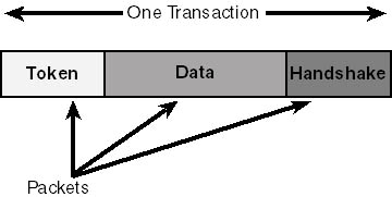
Figure 11-5. Phases of a bus transaction.
You'll notice that there's no handshake packet that means, "I found a transmission error in this transaction." Whoever is waiting for an acknowledgment is expected to realize that lack of acknowledgment implies an error and to retry the transaction. The USB designers believe that errors will be infrequent, by the way, which means that any occasional delay because of retries won't have a big effect on throughput.
In general, an endpoint can be in any of the states illustrated in Figure 11-6. In the Idle state, the endpoint is ready to process a new transaction initiated by the host. In the Busy state, the endpoint is busy processing a transaction and can't handle a new one. If the host tries to initiate a transaction to a busy endpoint (other than a control endpoint, as described in the next section), the device will respond with a NAK handshake packet to cause the host to retry later. Errors that the device detects in its own functionality (not including transmission errors) cause the device to send a STALL handshake packet for its current transaction and to enter the Stalled state. Control endpoints automatically unstall when they get a new transaction, but the host must send a clear feature control request to any other kind of endpoint before addressing another request to a stalled endpoint.
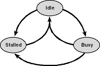
Figure 11-6. States of an endpoint.
A control transfer conveys control information to or from a control endpoint on a device. For example, one part of the overall process by which the operating system configures a USB device is performing input control transfers to read various descriptor structures kept onboard the device. Another part of the configuration process involves an output control transfer to establish one of the many possible configurations as current and to enable one or more interfaces. Control transfers are lossless in that the bus driver retries erroneous transfers up to three times before giving up and reporting an error status to upstream software. As indicated in Table 11-1, control endpoints must specify a maximum data transfer length of 8, 16, 32, or 64 bytes. An individual transaction can involve less data than the indicated maximum but not more.
Control transactions are a high priority in USB. A device isn't allowed to claim business as an excuse to avoid handling a control transaction. Moreover, the bus driver reserves up to 10 percent of each frame time for control transactions. Assuming a light enough load, therefore, the host can be sure of completing a control transaction within one millisecond. A heavier load, however, might force a pending control transaction into a later frame, with the result that higher latencies are possible.
Every device has at least one control endpoint numbered 0 that responds to input and output control transactions. Strictly speaking, endpoints belong to configurations, but endpoint 0 is an exception in that it terminates the default control pipe for a device. Endpoint 0 is active even before the device receives its configuration and no matter what other endpoints (if any) are available. A device need not have additional control endpoints besides endpoint 0 (although the USB specification allows for the possibility) because endpoint 0 can service most control requests perfectly well. If you define a vendor-specific request that can't complete within the frame, however, you should create an additional control endpoint to forestall having your onboard handler preempted by a new transaction.
Each control transaction includes a SETUP token, which can be followed by an optional data phase in which additional data moves to or from the device and a handshake phase in which the device responds with an ACK packet, a STALL packet, or not at all. See Figure 11-7. Devices are required to accept control transfers at all times and can therefore not respond with NAK to indicate a busy endpoint. Sending an invalid request to a control endpoint elicits a STALL response, but the device automatically clears the stall condition when it receives the next SETUP packet. This special case of stalling is called protocol stall in the USB specification—see Section 8.5.2.4.
The SETUP token that prefaces a control transfer consists of eight data bytes, as illustrated in Figure 11-8. In this and other data layout figures, I'm showing data bytes in the order in which they're transmitted over the USB wire, but I'm showing bits within individual bytes starting with the high-order bit. Bits are transmitted over the wire starting with the least-significant bit, but host software and device firmware typically work with data after the bits have been reversed. Intel computers and the USB bus protocols employ the little-endian data representation in which the least-significant byte of a multibyte data item occupies the lowest address. The 8051 microprocessor used in several USB chip sets, including the Anchor Chips chip set, is actually a big-endian computer. Firmware must therefore take care to reverse data bytes appropriately.
)
Figure 11-7. Phases of a control transfer.
)
Figure 11-8. Contents of a SETUP token.
Notice in the figure that the first byte of a SETUP token indicates the direction of information flow, a request type, and the type of entity that is the target of the control transfer. The request types are standard (defined as part of the USB specification), class (defined by the USB working group responsible for a given class of device), and vendor (defined by the maker of the device). Control requests can be addressed to the device as a whole, to a specified interface, to a specified endpoint, or to some other vendor-specific entity on the device. The second byte of the SETUP token indicates which request of the type indicated in the first byte is being made. Table 11-2 lists the standard requests that are currently defined. For information about class-specific requests, consult the appropriate device class specification. (See the first URL I gave you at the beginning of this chapter for information on how to find these specifications.) Device manufacturers are free to define their own vendor-specific request codes. For example, Anchor Chips uses the request code A0h to download firmware from the host.
NOTE
Note that control requests that affect the state of some particular endpoint are sent to a control endpoint and not to the endpoint whose state is affected.
Table 11-2. Standard device requests.
| Request Code | Symbolic Name | Description | Possible Recipients |
|---|---|---|---|
| 0 | GET_STATUS | Gets status information | Any |
| 1 | CLEAR_FEATURE | Clears a two-state feature | Any |
| 2 | (Reserved) | ||
| 3 | SET_FEATURE | Sets a two-state feature | Any |
| 4 | (Reserved) | ||
| 5 | SET_ADDRESS | Sets device address | Device |
| 6 | GET_DESCRIPTOR | Gets device, configuration, or string descriptor | Device |
| 7 | SET_DESCRIPTOR | Sets a descriptor (optional) | Device |
| 8 | GET_CONFIGURATION | Gets current configuration index | Device |
| 9 | SET_CONFIGURATION | Sets new current configuration | Device |
| 10 | GET_INTERFACE | Gets current alternate setting index | Interface |
| 11 | SET_INTERFACE | Enables alternate setting | Interface |
| 12 | SYNCH_FRAME | Reports synchronization frame number | (Isochronous) Endpoint |
The remainder of the SETUP packet contains a value code whose meaning depends on which request is being made, an index value with similarly mutable meaning, and a length field that indicates how many bytes of data are to be transferred during the data phase of the control transaction. The index field contains the endpoint or interface number when a control request addresses an endpoint or interface. A 0 value for the data length implies that this particular transaction has no data phase.
I'm not going to exhaustively describe all of the details of the various standard control requests; you should consult Section 9.4 of the USB specification for full information. I do want to briefly discuss the concept of a device feature, however. USB envisages that any of the addressable entities belonging to a device can have features that can be represented by the state of a single bit. Two such features are standardized for all devices.
The DEVICE_REMOTE_WAKEUP feature—a feature belonging to the device as a whole—indicates whether or not the device should use its ability (if any) to remotely wake up the computer when external events occur. Host software (specifically, the bus driver) enables or disables this feature by addressing a SET_FEATURE or CLEAR_FEATURE command, respectively, to the device and specifying a value code of 1 to designate the wake-up feature. The DDK uses the symbolic name USB_FEATURE_REMOTE_WAKEUP for this feature code.
The ENDPOINT_HALT feature—a feature belonging to an endpoint—indicates whether or not the endpoint is in the functional stall state. Host software can force an endpoint to stall by sending the endpoint a SET_FEATURE command with a value code of 0 to designate ENDPOINT_HALT. The firmware that manages the endpoint might independently decide to stall, too. Host software (once again, the bus driver) clears the stall condition by sending a CLEAR_FEATURE command with a value code of 0. The DDK uses the symbolic name USB_FEATURE_ENDPOINT_STALL for this feature code.
The USB specification does not prescribe ranges of device or endpoint feature codes for vendor use. To avoid possible standardization issues later, you should avoid defining device-level or endpoint-level features. Instead, define your own vendor-type control transactions. Notwithstanding this advice, later in this chapter I'll show you a sample driver (FEATURE) that controls the 7-segment LED display on the Anchor Chips development board. For purposes of that sample, I defined an interface-level feature numbered 42. (USB currently defines a few interface-level features for power management, so you would not want to emulate my example except for learning about how features work.)
A bulk transfer conveys up to 64 bytes of data to or from a bulk endpoint. Like control transfers, bulk transfers are lossless. Unlike control transfers, bulk transfers don't have any particular guaranteed latency. If the host has room left over in a frame after accommodating other bandwidth reservations, it will schedule pending bulk transfers.
Figure 11-9 illustrates the phases that make up a bulk transfer. The transfer begins with either an IN or an OUT token that addresses the device and endpoint. In the case of an output transaction, a data phase follows in which data moves from the host to the device and then a handshake phase in which the device provides status feedback. If the endpoint is busy and unable to accept new data, it generates a NAK packet during the handshake phase—the host will retry the output transaction later. If the endpoint is stalled, it generates a STALL packet during the handshake phase—the host must later clear the halt condition before retrying the transmission. If the endpoint receives and processes the data correctly, it generates an ACK packet in the handshake phase. The only remaining case is the one in which the endpoint doesn't correctly receive the data for some reason and simply doesn't generate a handshake—the host will detect the absence of any acknowledgment and automatically retry up to three times.
Following the IN token that introduces an input bulk transfer, the device performs one of two operations. If it can, it sends data to the host, whereupon the host either generates an ACK handshake packet to indicate error-free receipt of the data or stays mute to indicate some sort of error. If the host detects an error, the absence of an ACK to the device causes the data to remain available—the host will retry the input operation later on. If the endpoint is busy or halted, however, the device generates a NAK or STALL handshake instead of sending data. The NAK indicates that the host should retry the input operation later, and the STALL requires the host to eventually send a clear feature command to reset the halt condition.
)
Figure 11-9. Phases of a bulk or interrupt transfer.
An interrupt transfer is practically identical to a bulk transfer insofar as the operation of the bus and the device are concerned. It moves up to 64 bytes of data losslessly to or from an interrupt endpoint. The only difference between interrupt and bulk transfers has to do with latency. An interrupt endpoint specifies a polling interval in the range 1-255 milliseconds. The host reserves sufficient bandwidth to make sure of performing an IN or OUT transaction directed toward the endpoint at least as frequently as the polling interval.
NOTE
Note that USB devices don't generate asynchronous interrupts: they always respond to a poll. You might need to know that the Microsoft host controller drivers effectively round the polling interval specified in an interrupt endpoint descriptor down to a power of 2 no greater than 32. For example, an endpoint that specifies a polling interval of 31 milliseconds will actually be polled every 16 milliseconds. A specified polling interval between 32 and 255 milliseconds results in an actual polling interval of 32 milliseconds.
An isochronous transfer moves up to 1023 data bytes to or from an isochronous endpoint during every bus frame. Because of the guaranteed periodicity of isochronous transfers, they are ideal for time-sensitive data such as audio signals. The guarantee of periodicity comes at a price, however: isochronous transfers that fail because of data corruption don't get retried automatically. The USB designers assumed that isochronous data streams can tolerate occasional small losses.
An isochronous transaction consists of an IN or OUT token followed by a data phase in which data moves to or from the host. No handshake phase occurs because no errors are retried. See Figure 11-10.
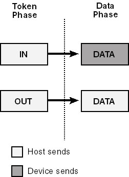
Figure 11-10. Phases of an isochronous transfer.
The host reserves up to 90 percent of the bus bandwidth for isochronous and interrupt transfers. In fact, system software needs to reserve bandwidth in advance to make sure that all active devices can be accommodated.
USB devices maintain onboard data structures known as descriptors to allow for self-identification to host software. Table 11-3 lists the different descriptor types. Each descriptor begins with a two-byte header containing the byte count of the entire descriptor (including the header) and a type code. As a matter of fact, if you ignore the special case of a string descriptor—concerning which, see "String Descriptors" a bit further on—the length of a descriptor is implied by its type because all descriptors of a given type have the same length. The explicit length is nonetheless present in the header to provide for future extensibility. Additional, type-specific data follows the fixed header.
In the remainder of this section, I'll describe the layout of each type of descriptor by using the data structures defined in the DDK (specifically, in USB100.H). The official rendition of this information is in Section 9.6 of the USB specification.
Table 11-3. Descriptor types.
| Descriptor Type | Description |
|---|---|
| Device | Describes an entire device |
| Configuration | Describes one of the configurations of a device |
| Interface | Describes one of the interfaces that's part of a configuration |
| Endpoint | Describes one of the endpoints belonging to an interface |
| String | Contains a human-readable Unicode string describing the device, a configuration, an interface, or an endpoint |
| Configuration | Describes power-management capabilities of a device power configuration |
| Interface power | Describes power-management capabilities of a device function |
Each device has a single device descriptor that identifies the device to host software. The host uses a GET_DESCRIPTOR control transaction directed to endpoint 0 to read this descriptor. The device descriptor has the following definition in the DDK:
typedef struct _USB_DEVICE_DESCRIPTOR {
  UCHAR bLength;
  UCHAR bDescriptorType;
  USHORT bcdUSB;
  UCHAR bDeviceClass;
  UCHAR bDeviceSubClass;
  UCHAR bDeviceProtocol;
  UCHAR bMaxPacketSize0;
  USHORT idVendor;
  USHORT idProduct;
  USHORT bcdDevice;
  UCHAR iManufacturer;
  UCHAR iProduct;
  UCHAR iSerialNumber;
  UCHAR bNumConfigurations;
} USB_DEVICE_DESCRIPTOR, *PUSB_DEVICE_DESCRIPTOR;
|
The bLength field in a device descriptor will equal 18, and the bDescriptorType field will equal 1 to indicate that it's a device descriptor. The bcdUSB field contains a version code (in binary-coded decimal) indicating the version of the USB specification to which this descriptor conforms. Current devices use the value 0x0100 or 0x0110 here to indicate conformance with the 1.0 or 1.1 specifications, respectively.
The values bDeviceClass, bDeviceSubClass, and bDeviceProtocol identify the type of device. Possible device class codes are defined by the USB specification and at the time of this writing include the codes listed in Table 11-4. Individual device class working groups within the USB committee define subclass and protocol codes for each device class. For example, the audio class has subclass codes for control, streaming, and MIDI streaming interfaces. And the mass storage class defines protocol codes for various methods of using endpoints for data transfer.
You can specify a class for an entire device or at the interface level, but in practice the device class, subclass, and protocol codes are often in an interface descriptor rather than in the device descriptor. (The device descriptor contains 0 for these codes in such cases.) USB also provides an escape valve for unusual types of devices in the form of the device class code 255. A vendor can use this type code to designate a nonstandard device for which the subclass and protocol codes provide the vendor-specific description. For example, a device built around the Anchor Chips chip set comes on line with a device descriptor having class, subclass, and protocol codes all equal to 255 to indicate an Anchor Chips default device. That device is primarily capable of accepting a vendor-specific control request to download firmware that will change the personality of the device to something else having its own (new) set of descriptors.
The bMaxPacketSize0 field of the device descriptor gives the maximum size of a data packet for a control transfer over endpoint 0. There isn't a separate endpoint descriptor for this endpoint (which every device has to implement), so this field is the only place where the number can be presented. Since this field is at offset 7 within the descriptor, the host can always read enough of the descriptor to retrieve this value even if endpoint 0 is capable only of the minimum size transfer (eight bytes). Once the host knows how big endpoint 0 transfers can be, it can structure subsequent requests appropriately.
The idVendor and idProduct fields specify a vendor code and a vendor-specific product identifier for the device. bcdDevice specifies a release number (such as 0x0100 for version 1.0) for the device. These three fields determine which driver the host software will load when it detects the device. The USB organization assigns vendor codes, and each vendor assigns its own product codes.
Table 11-4. USB device class codes.
| Symbolic Name | Class Code | Description |
|---|---|---|
| USB_DEVICE_CLASS_RESERVED | 0 | Indicates that class codes are in the interface descriptors |
| USB_DEVICE_CLASS_AUDIO | 1 | Devices used to manipulate analog or digital audio, voice, and other sound-related data (but not including transport mechanisms) |
| USB_DEVICE_CLASS_COMMUNICATIONS | 2 | Telecommunications devices such as modems, telephones, answering machines, and so on |
| USB_DEVICE_CLASS_HUMAN_INTERFACE | 3 | Human interface devices such as keyboards, mice, and so on |
| USB_DEVICE_CLASS_MONITOR | 4 | Display monitors |
| USB_DEVICE_CLASS_PHYSICAL_INTERFACE | 5 | HID devices involving real-time physical feedback, such as force-feedback joysticks |
| USB_DEVICE_CLASS_POWER | 6 | HID devices that perform power management, such as batteries, chargers, and so on |
| USB_DEVICE_CLASS_PRINTER | 7 | Printers |
| USB_DEVICE_CLASS_STORAGE | 8 | Mass storage devices, such as disk and CD-ROM |
| USB_DEVICE_CLASS_HUB | 9 | USB hubs |
| USB_DEVICE_CLASS_VENDOR_SPECIFIC | 255 | Vendor-defined device class |
The iManufacturer, iProduct, and iSerialNumber fields identify string descriptors that provide a human-readable description of the manufacturer, the product, and the unit serial number. These strings are optional, and a 0 value in one of these fields indicates the absence of the descriptor. If you put a serial number on a device, Microsoft recommends that you make it unique for each physical device.
Lastly, the bNumConfigurations field indicates how many configurations the device is capable of. Microsoft drivers work only with the first configuration (number 1, that is) of a device. I'll explain later, in "Configuration," what you might do for a device that has multiple configurations.
Each device has one or more configuration descriptors that describe the various configurations of which the device is capable. System software reads a configuration descriptor by performing a GET_DESCRIPTOR control transaction addressed to endpoint 0. The DDK defines the configuration descriptor structure as follows:
typedef struct _USB_CONFIGURATION_DESCRIPTOR {
  UCHAR bLength;
  UCHAR bDescriptorType;
  USHORT wTotalLength;
  UCHAR bNumInterfaces;
  UCHAR bConfigurationValue;
  UCHAR iConfiguration;
  UCHAR bmAttributes;
  UCHAR MaxPower;
} USB_CONFIGURATION_DESCRIPTOR, *PUSB_CONFIGURATION_DESCRIPTOR;
|
The bLength and bDescriptorType fields will be 9 and 2, respectively, to indicate a configuration descriptor nine bytes in length. The wTotalLength field contains the total length of this configuration descriptor plus the interface and endpoint descriptors that are part of the configuration. In general, the host performs one GET_DESCRIPTOR request to retrieve the nine-byte configuration descriptor proper and then another GET_DESCRIPTOR request specifying this total length. The second request, therefore, transfers the grand unified descriptor. (It's impossible to retrieve interface and endpoint descriptors except as part of a configuration descriptor.)
The bNumInterfaces field indicates how many interfaces are part of the configuration. The count includes just the interfaces themselves, not each alternate setting of an interface. The purpose of this field is to allow for multifunction devices such as keyboards that have embedded locator (mouse and the like) functionality.
The bConfigurationValue field is an index that identifies the configuration. You use this value in a SET_CONFIGURATION control request to select the configuration. The first configuration descriptor for a device has a 1 here. (Selecting configuration 0 puts the device in an unconfigured state in which only endpoint 0 is active.)
The iConfiguration field is an optional string descriptor index pointing to a Unicode description of the configuration. Zero indicates the absence of a string description.
The bmAttributes byte contains a bit mask describing power and perhaps other characteristics of this configuration. See Table 11-5. The unmentioned bits are reserved for future standardization. A configuration supporting remote wake-up would have the remote wake-up attribute set. The high-order two bits interact with the MaxPower field of the configuration descriptor to describe the power characteristics of the configuration. Basically, every configuration sets the high-order bit (which used to mean the device was powered from the bus) and also sets MaxPower to the maximum number of two milliamp power units that it will draw from the bus. A configuration that uses some local power will also set the self-powered attribute bit.
Table 11-5. Configuration attribute bits.
| Bit mask | Symbolic Name | Description |
|---|---|---|
| 80h | USB_CONFIG_BUS_POWERED | Obsolete—should always be set to 1 |
| 40h | USB_CONFIG_SELF_POWERED | Configuration is self-powered |
| 20h | USB_CONFIG_REMOTE_WAKEUP | Configuration has a remote wake-up feature |
Each configuration has one or more interface descriptors that describe the interface(s) that provide device functionality. System software can fetch an interface descriptor only as part of a GET_DESCRIPTOR control request that retrieves the entire configuration descriptor of which the interface descriptor is a part. The DDK defines the interface descriptor structure as follows:
typedef struct _USB_INTERFACE_DESCRIPTOR {
  UCHAR bLength;
  UCHAR bDescriptorType;
  UCHAR bInterfaceNumber;
  UCHAR bAlternateSetting;
  UCHAR bNumEndpoints;
  UCHAR bInterfaceClass;
  UCHAR bInterfaceSubClass;
  UCHAR bInterfaceProtocol;
  UCHAR iInterface;
} USB_INTERFACE_DESCRIPTOR, *PUSB_INTERFACE_DESCRIPTOR;
|
The bLength and bDescriptorType fields will be 9 and 4, respectively, to indicate an interface descriptor nine bytes in length. bInterfaceNumber and bAlternateSetting are index values that can be used in a SET_INTERFACE control transaction to specify activation of the interface. These numbers are essentially arbitrary, but it's customary to number the interfaces within a configuration starting with zero and to number the alternate settings of each interface starting with zero, too.
The bNumEndpoints field indicates how many endpoints—other than 0, which is assumed to always be present—are part of the interface.
The bInterfaceClass, bInterfaceSubClass, and bInterfaceProtocol fields describe the functionality provided by the interface. A nonzero class code should be one of the device class codes I discussed earlier, in which case the subclass and protocol codes would have the same meaning as well. Zero values in these fields are not allowed at the present time—zero is reserved for future standardization.
Finally, iInterface is the index of a string descriptor containing a Unicode description of the interface. Zero indicates that no string is present.
Each interface has zero or more endpoint descriptors that describe the endpoint(s) that handle transactions with the host. System software can fetch an endpoint descriptor only as part of a GET_DESCRIPTOR control request that retrieves the entire configuration descriptor of which the endpoint descriptor is a part. The DDK defines the endpoint descriptor structure as follows:
typedef struct _USB_ENDPOINT_DESCRIPTOR {
  UCHAR bLength;
  UCHAR bDescriptorType;
  UCHAR bEndpointAddress;
  UCHAR bmAttributes;
  USHORT wMaxPacketSize;
  UCHAR bInterval;
} USB_ENDPOINT_DESCRIPTOR, *PUSB_ENDPOINT_DESCRIPTOR;
|
The bLength and bDescriptorType fields will be 7 and 5, respectively, to indicate an endpoint descriptor of length seven bytes. bEndpointAddress encodes the directionality and number of the endpoint, as illustrated in Figure 11-11. For example, an address value of 0x82 denotes an IN endpoint numbered 2, and an address of 0x02 denotes an OUT endpoint that's also numbered 2. Except for endpoint 0, you can have two different endpoints that share the same number but perform transfers in the opposite direction.
)
Figure 11-11. Bit assignments within an endpoint descriptor's address field.
The low-order two bits of bmAttributes indicate the type of the endpoint. See Table 11-6. The remaining bits are reserved for future standardization and should currently be set to 0.
Table 11-6. Type codes for endpoints.
| Symbolic Name | Value | Endpoint Type |
|---|---|---|
| USB_ENDPOINT_TYPE_CONTROL | 0 | Control endpoint |
| USB_ENDPOINT_TYPE_ISOCHRONOUS | 1 | Isochronous endpoint |
| USB_ENDPOINT_TYPE_BULK | 2 | Bulk transfer endpoint |
| USB_ENDPOINT_TYPE_INTERRUPT | 3 | Interrupt endpoint |
The wMaxPacketSize value indicates the largest amount of data the endpoint can transfer during one transaction. Table 11-1 lists the possible values for this field for each type of endpoint. (Even though Table 11-1 explicitly concerns transfer types, note that endpoint types map one to one with transfer types.) For example, a control or bulk endpoint would specify one of the values 8, 16, 32, or 64. An interrupt endpoint would specify a value in the range 0-64, inclusive. An isochronous endpoint would specify a number less than 1024.
Interrupt and isochronous endpoint descriptors also specify a polling interval measure in milliseconds in the bInterval field. This number indicates how often the host should poll the endpoint for a possible data transfer. For an interrupt endpoint, it can range from 1 to 255 and represents the maximum period between polls. An isochronous endpoint should specify 1 because it's polled during every frame—once per millisecond, in other words.
A device, configuration, or endpoint descriptor contains optional string indices that identify human-readable strings. The strings themselves are stored on the device in Unicode in the form of USB string descriptors. System software can read a string descriptor by addressing a GET_DESCRIPTOR control request to endpoint 0. The DDK declares the string descriptor structure as follows:
typedef struct _USB_STRING_DESCRIPTOR {
  UCHAR bLength;
  UCHAR bDescriptorType;
  WCHAR bString[1];
} USB_STRING_DESCRIPTOR, *PUSB_STRING_DESCRIPTOR;
|
The bLength value is variable, depending on how long the string data is. The bDescriptorType field will be 3 to indicate that this is a string descriptor. The bString data contains the string data itself. Any null terminator would be included in the descriptor length.
USB devices can support strings in multiple languages. String number 0 is an array of supported language identifiers rather than a character string. (A string index of 0 used in another descriptor denotes the absence of a string reference. Thus, index number 0 is available for this special use.) The language identifiers are of the same LANGID type that Win32 programs use. For example, 0x0409 is the code for American English. The USB specification doesn't prescribe what happens if you ask a device to return a string descriptor for a language that the device doesn't advertise supporting, so you should read the string-zero array before issuing requests for string descriptors. Consult Section 9.6.5 of the USB specification for more information about language identifiers.
USB is an evolving specification, and I can present only a snapshot of its evolution at the time of writing. A USB working group recently finalized a specification for interface-level power management, for example. You can read about it at the USB Web site, and the DDK header file USB100.H contains definitions for it. Time doesn't permit us (me and the publisher, that is) to explore the ramifications of this new facility. Luckily, it would appear that WDM driver writers don't need to know about them—interpreting Interface Feature descriptors is the province of the hub driver rather than a WDM function or filter driver.