(The D-Sub connector is female.)
Keywords:
USB, LPT, parallel, parallel port, printer port, converter, adaptor
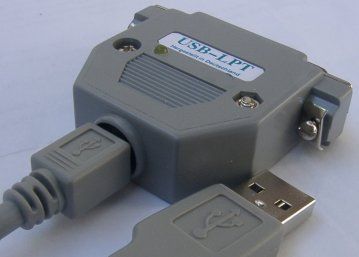
- Converter from USB to parallel port (25 pin SubD receptacle)
with hardware virtualization at input/output instruction level
- Supports all parallel port modes named SPP, EPP and ECP, 16 Byte FIFO depth
- USB Low Speed (1.5 Mbit/s signaling; 1 kByte/s for input/output instructions)
- Supports USB suspend mode with reduced power consumption
- Full open-source, even for schematics and PCBs
To USB2LPT — Overview
USB2LPT – Cloning instructions for Release 1.6
This device is almost the same as Release 1.5.
For high-speed USB, there is a Release 1.7.
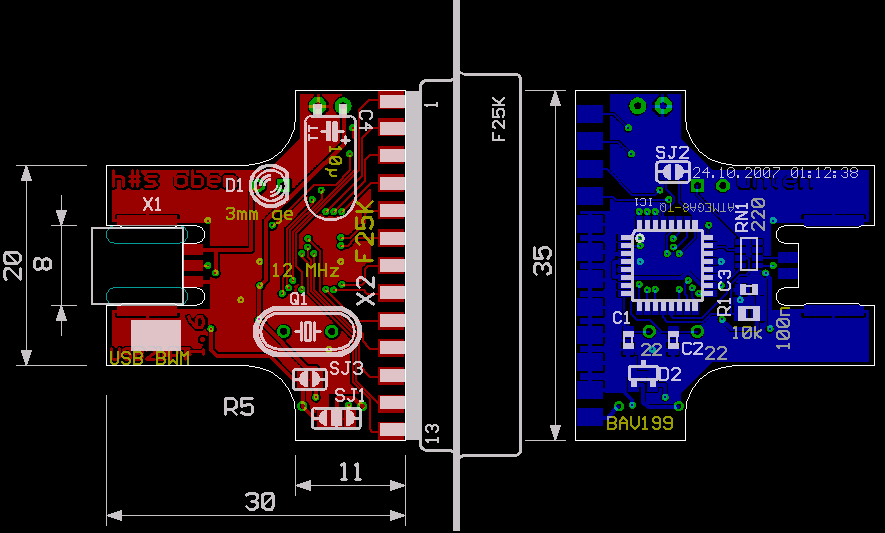
If 3.3V operation of ATmega is wanted, a user can now populate a dual diode BAV199
instead of the LD1117 of the previous version.
This enables drawing less than 500 µA of standby current in this case.
 The firmware from december 2010 to february 2012 is not compatible to Windows Vista and Windows 7 (32 and 64 bit) – please update!
Electronic Components
You need:
| Pieces | Description | Reichelt Order Code | Price in € (2007)
|
|---|
| 1 | ATmega8 in TQFP32 package | ATMEGA 8-16 TQ | 1.70
|
| 1 | Ceramic capacitor 100 nF 0603 | X7R-G0603 100n | 0.051
|
| 1 | Resistor array 220 Ω 1206 | BCN16 220 | 0.02
|
| 1 | Resistor 10 kΩ 0805 | SMD-0805 10k | 0.10
|
| 1 | Electrolytic capacitor 10 µF | rad 10/35 | 0.041
|
| 1 | Yellow LED 3 mm | LED 3mm ge | 0.051
|
| 1 | SubD receptacle 25 pin | D-SUB BU 25 | 0.15
|
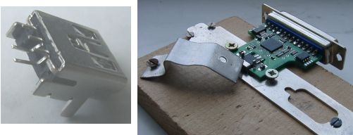
| 1 | USB receptacle MiniB through-hole | USB BWM | 0.50
|
| 1 | Housing | Kappe CG25G | 0.13
|
| 1 | USB cable 1 m | AK 673-A | 0.98
|
| 1 | Two-sided PCB (see below) | UL16LP | 1.00
|
It's not hard to populate this PCB.
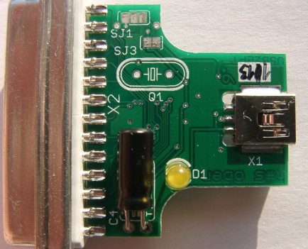
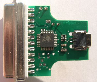
(Sufficiently) populated PCB
The LED
The yellow multi-function LED shows following states:
- off:
- No power supply (cable broken or similar)
- USB2LPT not recognized by computer
- USB Standby mode - e.g. at notebook's suspend mode
- USB2LPT in bootloader mode
- on:
- USB2LPT active, output drivers enabled, inputs with pull-up resistors
- flashing:
- fast: USB BULK or INTERRUPT transfers (redirected IN and OUT instructions; normal operation)
- slow: USB CONTROL transfers (mostly initiated by Windows)
Software
Here are some notes about firmware implementation:
The current USB2LPT Low-Speed (1.6) firmware implementation has many ways for I/O transaction.
However, the driver (usb2lpt.sys) preferes only one, the oldest and still fastest way, using two BULK pipes.
One BULK OUT for addresses and output (write) data, another BULK IN for input (read) data.
Refer to DeviceIoControl() based API for understanding.
The other ways for I/O transactions exist for following reasons:
- The very simple and low-performance EP0 based for one Linux user (Henning Paul).
Contrary to all other interfaces, it has no ECP/EPP support at all.
I never used this interface.
- The INTERRUPT OUT + IN alternative for Linux, Vista, Win7 to conform
to USB standard which forbids BULK for low-speed USB devices.
(USB2LPT was developed for full-speed AN2313 controller.)
The device is preconfigured to use INTERRUPT instead of BULK.
This works on all known systems but is at least 8 times slower than BULK.
Activating BULK will remove that slowdown but will render the entire device
as defective in Windows Vista, 7, 8, and newer, and Linux.
The usb2lpt.sys driver supports both BULK and INTERRUPT pipes.
- The advanced EP0 based as a faster alternative to INTERRUPT pipes.
The driver currently doesn't use this way, but it's planned.
- The HID (Human Interface Device) way to overcome the driver
certification trouble on Win64 systems.
The driver cannot use this way because Windows loads its generic
HID driver for this interface (that omits certification hassle).
This interface is for USB2LPT-adopted
inpout32.dll
and similar port access libraries.
Note that most parallel port accessing software will not run on 64 bit systems,
even with a true parallel port.
In such cases, requiring to use InpOut32.dll is not a limitation.
Preparations
- Drill holes into SubD shell for LED
- Label the shell
- Bend pins of USB receptacle straight – see picture
- Trim pins of LED and electrolytic capacitor to about 1 cm length
- Download and install either
PonyProg or
WinAVR
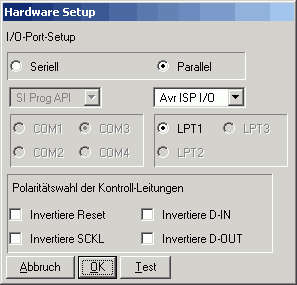
- PonyProg: Setup interface
as shown here,
check by connecting the programming adapter
(this checks for connection between Pin 2 and Pin 12),
invoke Setup→Calibration
Making-Of
New: The do-it-yourself process for the similar 1.7 version is available at YouTube!
(Three parts, running time ca. 30 minutes, German comments, English subtitling)
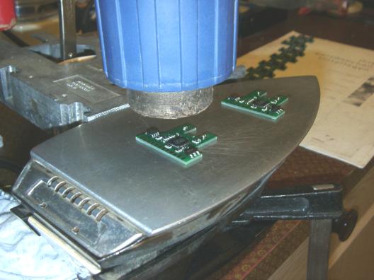
- Solder paste applying, SMD population
- SMD population (cont.), Reflow process, SubD receptacle
- USB receptacle, LED, Housing shell, Final check
- put SMD cream, 4 SMD components, make a
reflow process – or solder by hand
- Check for short circuit between 5 volts and ground
- press and solder SubD receptacle keeping ½ mm gap between PCB and SubD shroud
- Align and solder USB receptacle (see helper tool),
solder the pins with lowest possible iron temperature
- Populate electrolytic capacitor as flat as possible
- Align and solder the LED using the shell, watch for right polarity
- Check for short circuit between 5 volts and ground again
- Check “operation” by connecting the USB cable, must show as
“inoperational USB device”, this is the power supply for programming
the bootloader
- Connect programming adapter to an old-style
parallel port and program the bootloader, either
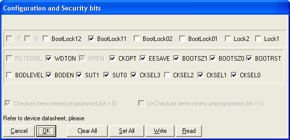
- PonyProg: load
main.hex, write,
set fuses exactly as shown here
Do not twiddle with the fuses without knowledge! You may make the ATmega unaccessible to PonyProg and all other low-voltage serial programmers!
or
- WinAVR: invoke
make prog
(directory src/firmware/USB2LPT6/bootloadHID)
If your programming software doesn't recognize the right controller, check:
- Programming adapter soldered correctly?
- Programming adapter used in correct direction?
- Solder jumper SJ2 (still) connected?
- Pins of SubD25 socket soldered correctly?
- Microcontroller soldered in correct alignment and angle?
(If wrong, remove with a hot-air gun.
If 180° wrong, use new ATmega8.)
- Mikrocontroller soldered without shorts?
- Cycle power to USB2LPT,
let install driver
usb2lpt.inf.
The Bootloader (
HIDboot)
will not occur because the .hex file above contains both bootloader and the real USB2LPT firmware.
If there is no USB2LPT, then check:
- Solder joints on USB socket correctly?
- USB socket not melted? (Contact springs still visible?)
- SMD solder joints correctly without shorts?
Check with another computer and/or with front-side or back-side USB connectors on PC, or using a USB hub.
If USB2LPT seems to work unreliable, populating the crystal and downgrading to USB2LPT 1.5 firmware may help.
The reason is an unstable 5V supply, that jitters the internal RC oscillator of the 1.6 firmware solution.
- Remove programming adapter
- Scratch jumper SJ2 (the only solder jumper on silk-screen-less lower PCB side)
- Connect LPT checker or similar device,
run
Kurzschlusstest.exe, make corrections if necessary
Alternatively, download fw-utils.en.zip first for English message utilities (it's not supported by me).
- Close shell, make a final check
Known PCB bugs
- The crystal and the both 22 pF capacitors are not to populate
- Population with ATmegaX8 is currently not recommended.
If you want ATmega48 population, R1 should be 4.7 kΩ,
and the older firmware USB2LPT5 (and crystal) must be used.
A bootloader cannot be used (this chip has no bootloader support)
- If D2 (BAV199) is used, R1 must be 1.5 kΩ
- The 5 V USB interface with 220 Ω series resistors is incompatible to some notebooks.
In such a case, the device will not be recognized correctly, and you see „Unknown device“.
No driver installation will help here, and any force may damage your Windows installation.
Possible solutions:
- Use a USB hub in between, or an active extension cable (which is essentially a one-port hub).
- Change components to 3.3 V design, i.e. populate the BAV199 as stated above.
Of course, this will result in 3.3 V I/O voltages, and the inputs are then not truly 5.0 V compliant.
- Populate flying 3.9 V zener diodes to USB D+ and D- wires.
Solder jumpers
This revision 6 (USB2LPT 1.6) has 3 pre-connected solder jumpers:
- SJ1 can assign power to pin 25 of SubD receptacle:
- open: Pin 25 unbeschaltet
- right connected: Pin 25 to ground (default)
- left connected: Pin 25 to 5 volts
If power is needed, populating a self-resetting fuse is highly recommended.
- SJ2, connected at PCB fabrication,
scratched at device manufacturing: activates the RESET pin of ATmega
for programming the microcontroller.
- SJ3, connected by default, scratch when you want
3.3 volts operation of ATmega8 (e.g. for safer JTAG connection),
populate a BAV199 and change R1.
Moreover, scatch it to measure device's current consumption and re-solder.