For the need of capturing and post-processing parallel printer data,
additional hardware is needed in any circumstance.
Construction
With an FT245R
by FTDI,
the solution of this problem is surprisingly simple.
This integrated circuit contains a bi-directional USB-to-parallel FIFO,
and within MS Windows, a serial COM port occurs, that eases programming tasks.
And the most beautiful thing using USB is not to need any further power supply.
Using FT245R (bear in mind the suffix R, it's important!)
delivers a COM port for free, even on Windows 64 bit and Linux
(FTDI tends to make their drivers pretty good)
saves the quartz crystal and many other components of competitive solutions
saves oneself programming a microcontroller
enables fine-tuning of USB descriptors using accompanying FT-Tool for personalization
allows high data transfer rates at USB limit (Full-Speed USB)
facilitate true 5 V TTL levels at peripheral side
A parallel port emitting print data expects following conditions:
BUSY is HIGH while printer's input buffer is full, else LOW
ERR (error) must be HIGH permanently (no error)
PE (paper end) must be LOW permanently (no paper end)
ACK (acknowledge) transits twice with every transferred byte to LOW and HIGH
The 8-bit parallel printer data is eventually transferred by a LOW pulse at
STROBE, that's all.
The lines INIT,
SELIN,
AUTOFD
are out of concern.
See also parallel port article
at Wikipedia, and the BeyondLogic article.
Schematic (Eagle source)
Even though the inactive level for WR
is documented as LOW, applying a permanent HIGH level works too.
So, you can wire STROBE directly, without inversion.
The opposite FIFO data transfer direction of FT245R is disabled.
The purpose of the pull-up resisitor R1 at
WR
is solely for avoiding FIFO fill-in while cable connect or disconnect.
All the peripheral side pins of IC1 are protected by series resistors
RN1, RN2, and RN3 to avoid excess
ringing
introduced by
signal reflection
on possibly long or bad printer cables.
The resistor RN1B is a left-over from one resistor array,
and connected on one side to ease PCB routing (see board below).
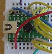
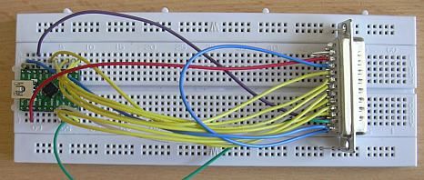
Evaluation construction
For evaluation, I used a ready-to-use
FT245R module by Siphec,
and a
wiring board.
I omitted the series resistors,
thus you shouldn't use parallel port extension cords to avoid ringing.
This FT245R module is a good choice for those who are frightened soldering
such small components with 0.5 mm pitch.
PCB design (Eagle source)
and part list (AKA BOM, bill of material)
The PCB above is made for fitting in a usual plastic D-Sub shell.
This design is similar to USB2LPT;
especially the USB-miniB receptacle is edge-mounted, see this
YouTube video clip
for how-to-do this.
The PCB can be easily home-made and is optimized for minimum vias.
It's even possible to produce a single-sided PCB using the same design
and to use wire straps.
Moreover, it's even possible not to drill any hole, applying the wire straps
on the component side (except one for GND that must connect to bottom-side
contacts of the D-Sub connector).
All components are located on top side.
Note: The schematic's pin numbers of FT245R don't apply to the L package
(SSOP, 28-pin, 0.65 mm pitch), and re-design of PCB would be necessary.
Related
There are some gadgets having both USB and parallel port:
h#s USB2LPT,
provides a parallel port, especially for newer notebooks,
for programming devices and other home-made gadgets, not for printers
h#s LPTzUSB,
enables printing to a USB printer using an old-style parallel port,
competitive products are listed at the end of that web page
Moreover, there are solutions using Ethernet instead of USB, like
this.
LptCap is not intended for capturing local printer data.
Although such a constellation will work too, there are software-only
solutions around, like DosPrn,
or some methods available for the current operating system.
Someone (Sandro Bureca)
reported 100 kByte/s transfer rate,
but did not note which data source he had used.
Besides using FT245R the more general but more cumbersome solution is using
a microcontroller and firmware. It's possibly cheaper. For example:
In case of somehow too-standard-conforming printing devices
expecting BUSY and ACK cycles,
some glue logic is necessary that makes the construction by far more complex.
Note that only slow printers have time to generate this signaling.
Schematic with two 4 µs monoflops generating BUSY and
ACK
The Eagle source, in this case, contains only a valid schematic, no board.
Someone
reported me that one specific device requires that extra effort.
Another solution using Arduino board
8-bit Arduino boards are well suited for this task:
I prefer using the cheap Pro Micro board with its ATmega32U4.
Its firmware will consist mainly of the following code:
;ISR at Hi-Lo transition at Strobe (here: Input Capture at PD4)
;UENUM is preset with endpoint number for the USB-CDC IN channel,
;registers R16, R17, and flags are free for fast reaction on Strobe edge
	sbi	PORTD,1		;BUSY high
	in	r16,PINB	;(available) D1..D6
	in	r17,PIND	;residual D0 und D7
	andi	r16,0x7E
	andi	r17,0x81
	or	r16,r17		;concatenate
	sts	UEDATX,r16	;send to USB-CDC
	in	r16,UEINTX
	sbrc	r16,5		;check RWAL: FIFO full?
	 rjmp	1f		;no, to ACK cycle
 	ldi 	r16,0x7F
	sts	UEINTX,r16	;send data block (clear FIFOCON)
	in	r16,UEINTX
	sbrs	r16,5		;check RWAL: New (double-buffered) bank available?
	 rjmp	2f		;no, leave BUSY high, main loop must resolve
1:	cbi	PORTD,1		;BUSY low
 	cbi 	PORTC,6	 	;!ACK low
	ldi	r16,16
1:	dec	r16 		;wait 3 µs
	brne	1b
	sbi	PORTC,6		;!ACK high
2:	reti			;done
I implement this only on request!
Therefore, there is currently no firmware
nor sketch
available for download.
Application
For capturing printer data in a casual or long-term application,
there is HyperTerminal
and its capture-and-save menu item.
The baud rate for the COM port is a don't-care, as for any FT245
(or ATmega32U4 based USB-CDC) application.
However, if you want to redirect printer data to another Windows printer
(e.g. a PDF generator), if necessary with processing
ESC/P printer control codes,
I had written the application
SPE = Serial Printer Emulator.
The name implies that, while running this application service-like,
it converts the computer to (at least) one printer with a serial port,
together with the hardware described above, with a parallel port.
Of course you can write any application using any programming language you know,
that can read and process data from a COM port,
e.g. using VisualBasic, VBA, C++, Python or LabVIEW.