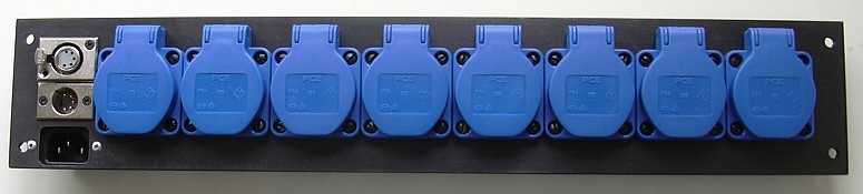
Simple DMX Dimmer
An eight-channel DMX dimmer with triacs, suitable for powering
resistive and auch inductive loads, in opposite to
DMX-Dimmer by Digital Enlightenment
(this one needs fast fuses to protect the triacs).
It's important here to keep it simple! No unnecessary components.
Therefore, typical components of such a device are omitted:
- No differencial amplifier 75176 on input.
This chip requires some insulated power supply.
Instead, the opto coupler is fed directly,
so we get a partial termination effect known from IDE hard disks
- No transformer for the microcontroller.
Such a transformer eats up space and noticeable quiescent power.
- No insulation between microcontroller and the mains supply.
This omits the typical MOC2032 (opto triacs) and simplifies detection
of zero crossings for the current.
So, this solution can safely operate with inductive loads.
Of course, the DMX input is insulated from mains supply.
- Tiniest possible microcontroller selected: ATtiny2313, all port pins are used up.
Nevertheless, all 512 DMX addresses can be selected by DIP switches.
- Combined zero crossing detector and gate-firing output sharing one
controller pin. No protection measures.
Microcontroller are cheap enough.
When one is blown (due to defective triac), you can plug in the next one.
An IC socket should be populated here.
- The dioded D10..D17 are necessary. Usual triacs have a low-value
resistance of about 100 Ω betwen gate and “Cathode”.
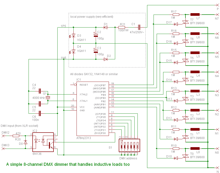
Schematic
Functional Description
The microcontroller is operated with 3 V supply,
symmetrical ± 1.5 V.
The ports PB0 upto PB7 are inputs most of the time.
These detect zero crossings of voltage (when triac is non-conducting)
or current (when triac is conducting).
So each input can synchronize to mains frequency,
even when three-phase systems are used.
(In this case, the microcontroller's supply potential must be N.)
While triac is conducting, the current zero cross will be used to detect
the phase lag of an inductive load, for calculating the next firing.
The resistors R10 upto R17 have so much resistance that
triacs T0 upto T7 are never fired,
however, at least ± 0.7 V are availale on the microcontroller's port pins.
The diodes D10..D17 limit the negative voltage to – 0.7 V.
The internal gate protection diodes limit the voltage to about + 2.2 V.
If you are in doubt, use two anti-parallel diodes for D10..D17.
For firing a triac, the port pin is reprogrammed to an output with low level.
Internal port resistance should suffice for gate current limiting,
so there is no external resistor.
If you decided to use anti-parallel diodes for D10..D17,
firing with positive and negative pulses allows better usage of the energy
stored in the electrolytic capacitors C2 and C3,
because these are charged in advance by the capacitor C1.
This dimmer requires 8 adjances DMX Addresses out of the 512 byte
address space. Therefore, a 6-bit address is suitable.
This is done by a 6 position DIP switch and integrated pull-up resistors.
The symmetrical DMX signal is fed to the fast opto coupler 6N136
(cheaper and less power consuming than 6N137).
Negative signal level will be clipped by diode D0.
So the sender or cable “sees” a partial termination of 470 Ω;
multiple devices can be connected before a bus overload occurs.
The power supply is done with capacitive resistance C1
and voltage limiters.
The LEDs D3 and D4 operate as zener diodes.
Their lighing can be used as an operation control.
The quartz crystal oscillator cannot be omitted (except by a ceramic resonator).
The operating voltage is not stable enough for reliable operation of the internal
RC oscillator, and RS-232 requires tight tolerances.
For the RS-232 receiver with 250 kBaud, 2 MHz are required at least.
The less the ATtiny's clock frequency, the less is the power consumption,
and the less (and cheaper) would be C1.
Why not a USB dimmer?
USB dimmer, using cheap ATtiny or ATmega microcontrollers,
require a two-chip solution, because of the tight time constraints
of both the V-USB and the zero-crossing detection and firing side.
In between you would place this opto coupler.
Therefore: USB dimmer have same complexity as one
USB→DMX converter
and one DMX dimmer.
(You will notice that DMX is invented for mains-connected circuitry!)
If you decide to use (more expensive) microcontrollers with built-in USB hardware
you need a bunch of opto couplers to the triacs. This tends to be expensive too.
Firmware
Not available, missing yet. Also the circuitry is not tested at all.