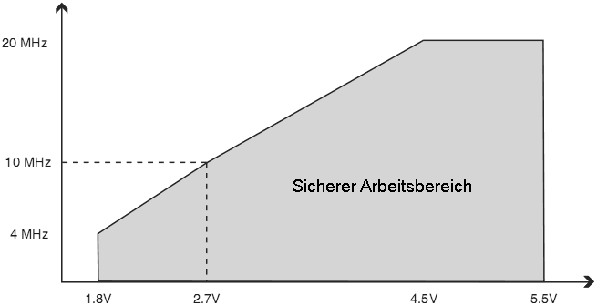
Bild 29-1: Maximale Frequenz vs. UCC

|
Betriebstemperatur: ................. -55 °C bis +125 °C Lagertemperatur: .................... -65 °C bis +150 °C
Spannung an jedem Pin außer RESET
Spannung an RESET Maximale Speisespannung: .......................... 6,0 V Gleichstrom pro I/O-Pin: .......................... 40,0 mA Gleichstrom an UCC und Massepins: .......... 200,0 mA |
|
| Symbol | Parameter | Bedingung | Min. | Typ.(2)| Max. | Einheit
| ICC
| Strom der Stromversorgung (1)
| Aktiv 1 MHz, UCC = 2 V | 0,2 | 0,55 | mA
| Aktiv 4 MHz, UCC = 3 V | 1,2 | 3,5 | mA
| Aktiv 8 MHz, UCC = 5 V | 4,0 | 12 | mA
| Idle 1 MHz, UCC = 2 V | 0,03 | 0,5 | mA
| Idle 4 MHz, UCC = 3 V | 0,21 | 1,5 | mA
| Idle 8 MHz, UCC = 5 V | 0,9 | 5,5 | mA
| Leistung-weg-Modus (3)
| 32 kHz TOSC laufend, UCC = 1,8 V | 0,75 | µA
| 32 kHz TOSC laufend, UCC = 3 V | 0,9 | µA
| Leistung-spar-Modus (3)
| Watchdog ein, UCC = 3 V | 3,9 | 15 | µA
| Watchdog aus, UCC = 3 V | 0,1 | 2 | µA
| |
|---|
| Symbol | Parameter | Bedingung | Min. | Typ.(2)| Max. | Einheit
| ICC
| Strom der Stromversorgung (1)
| Aktiv 1 MHz, UCC = 2 V | 0,2 | 0,5 | mA
| Aktiv 4 MHz, UCC = 3 V | 1,2 | 2,5 | mA
| Aktiv 8 MHz, UCC = 5 V | 4,0 | 9 | mA
| Idle 1 MHz, UCC = 2 V | 0,03 | 0,15 | mA
| Idle 4 MHz, UCC = 3 V | 0,21 | 0,7 | mA
| Idle 8 MHz, UCC = 5 V | 0,9 | 2,7 | mA
| Leistung-weg-Modus (3)
| 32 kHz TOSC laufend, UCC = 1,8 V | 0,75 | µA
| 32 kHz TOSC laufend, UCC = 3 V | 0,9 | µA
| Leistung-spar-Modus (3)
| Watchdog ein, UCC = 3 V | 3,9 | 8 | µA
| Watchdog aus, UCC = 3 V | 0,1 | 2 | µA
| |
|---|
| Symbol | Parameter | Bedingung | Min. | Typ.(2)| Max. | Einheit
| ICC
| Strom der Stromversorgung (1)
| Aktiv 1 MHz, UCC = 2 V | 0,2 | 0,55 | mA
| Aktiv 4 MHz, UCC = 3 V | 1,2 | 3,5 | mA
| Aktiv 8 MHz, UCC = 5 V | 4,1 | 12 | mA
| Idle 1 MHz, UCC = 2 V | 0,03 | 0,5 | mA
| Idle 4 MHz, UCC = 3 V | 0,18 | 1,5 | mA
| Idle 8 MHz, UCC = 5 V | 0,8 | 5,5 | mA
| Leistung-weg-Modus (3)
| 32 kHz TOSC laufend, UCC = 1,8 V | 0,8 | µA
| 32 kHz TOSC laufend, UCC = 3 V | 0,9 | µA
| Leistung-spar-Modus (3)
| Watchdog ein, UCC = 3 V | 3,9 | 15 | µA
| Watchdog aus, UCC = 3 V | 0,1 | 2 | µA
| |
|---|
| Symbol | Parameter | Bedingung | Min. | Typ.(2)| Max. | Einheit
| ICC
| Strom der Stromversorgung (1)
| Aktiv 1 MHz, UCC = 2 V | 0,2 | 0,5 | mA
| Aktiv 4 MHz, UCC = 3 V | 1,2 | 2,5 | mA
| Aktiv 8 MHz, UCC = 5 V | 4,1 | 9 | mA
| Idle 1 MHz, UCC = 2 V | 0,03 | 0,15 | mA
| Idle 4 MHz, UCC = 3 V | 0,18 | 0,7 | mA
| Idle 8 MHz, UCC = 5 V | 0,8 | 2,7 | mA
| Leistung-weg-Modus (3)
| 32 kHz TOSC laufend, UCC = 1,8 V | 0,8 | µA
| 32 kHz TOSC laufend, UCC = 3 V | 0,9 | µA
| Leistung-spar-Modus (3)
| Watchdog ein, UCC = 3 V | 3,9 | 8 | µA
| Watchdog aus, UCC = 3 V | 0,1 | 2 | µA
| |
|---|
| Symbol | Parameter | Bedingung | Min. | Typ.(2)| Max. | Einheit
| ICC
| Strom der Stromversorgung (1)
| Aktiv 1 MHz, UCC = 2 V | 0,2 | 0,55 | mA
| Aktiv 4 MHz, UCC = 3 V | 1,2 | 3,5 | mA
| Aktiv 8 MHz, UCC = 5 V | 4,2 | 12 | mA
| Idle 1 MHz, UCC = 2 V | 0,03 | 0,5 | mA
| Idle 4 MHz, UCC = 3 V | 0,2 | 1,5 | mA
| Idle 8 MHz, UCC = 5 V | 0,9 | 5,5 | mA
| Leistung-weg-Modus (3)
| 32 kHz TOSC laufend, UCC = 1,8 V | 0,75 | µA
| 32 kHz TOSC laufend, UCC = 3 V | 0,83 | µA
| Leistung-spar-Modus (3)
| Watchdog ein, UCC = 3 V | 4,1 | 15 | µA
| Watchdog aus, UCC = 3 V | 0,1 | 2 | µA
| |
|---|
| Symbol | Parameter | Bedingung | Min. | Typ.(2)| Max. | Einheit
| ICC
| Strom der Stromversorgung (1)
| Aktiv 1 MHz, UCC = 2 V | 0,2 | 0,5 | mA
| Aktiv 4 MHz, UCC = 3 V | 1,2 | 2,5 | mA
| Aktiv 8 MHz, UCC = 5 V | 4,2 | 9 | mA
| Idle 1 MHz, UCC = 2 V | 0,03 | 0,15 | mA
| Idle 4 MHz, UCC = 3 V | 0,2 | 0,7 | mA
| Idle 8 MHz, UCC = 5 V | 0,9 | 2,7 | mA
| Leistung-weg-Modus (3)
| 32 kHz TOSC laufend, UCC = 1,8 V | 0,75 | µA
| 32 kHz TOSC laufend, UCC = 3 V | 0,83 | µA
| Leistung-spar-Modus (3)
| Watchdog ein, UCC = 3 V | 4,1 | 8 | µA
| Watchdog aus, UCC = 3 V | 0,1 | 2 | µA
| |
|---|
| Symbol | Parameter | Bedingung | Min. | Typ.(2)| Max. | Einheit
| ICC
| Strom der Stromversorgung (1)
| Aktiv 1 MHz, UCC = 2 V | 0,3 | 0,55 | mA
| Aktiv 4 MHz, UCC = 3 V | 1,7 | 3,5 | mA
| Aktiv 8 MHz, UCC = 5 V | 5,2 | 12 | mA
| Idle 1 MHz, UCC = 2 V | 0,04 | 0,5 | mA
| Idle 4 MHz, UCC = 3 V | 0,3 | 1,5 | mA
| Idle 8 MHz, UCC = 5 V | 1,2 | 5,5 | mA
| Leistung-weg-Modus (3)
| 32 kHz TOSC laufend, UCC = 1,8 V | 0,8 | µA
| 32 kHz TOSC laufend, UCC = 3 V | 0,9 | µA
| Leistung-spar-Modus (3)
| Watchdog ein, UCC = 3 V | 4,2 | 15 | µA
| Watchdog aus, UCC = 3 V | 0,1 | 2 | µA
| |
|---|
| Symbol | Parameter | Bedingung | Min. | Typ.(2)| Max. | Einheit
| ICC
| Strom der Stromversorgung (1)
| Aktiv 1 MHz, UCC = 2 V | 0,3 | 0,5 | mA
| Aktiv 4 MHz, UCC = 3 V | 1,7 | 2,5 | mA
| Aktiv 8 MHz, UCC = 5 V | 5,2 | 9 | mA
| Idle 1 MHz, UCC = 2 V | 0,4 | 0,15 | mA
| Idle 4 MHz, UCC = 3 V | 0,3 | 0,7 | mA
| Idle 8 MHz, UCC = 5 V | 1,2 | 2,7 | mA
| Leistung-weg-Modus (3)
| 32 kHz TOSC laufend, UCC = 1,8 V | 0,8 | µA
| 32 kHz TOSC laufend, UCC = 3 V | 0,9 | µA
| Leistung-spar-Modus (3)
| Watchdog ein, UCC = 3 V | 4,2 | 8 | µA
| Watchdog aus, UCC = 3 V | 0,1 | 2 | µA
| |
|---|

| Frequenz | UCC| Temperatur | Kalibriergenauigkeit
| Werkskalibierung | 8,0 MHz | 3 V | 25 °C | ±10 %
| Anwenderkalibrierung | 7,3 - 8,1 MHz | 1,8V - 5.5 V | -40 °C - 85 °C | ±1 %
| |
|---|

| Symbol | Parameter | UCC = 1,8 - 5,5 V | UCC = 2,7 - 5,5 V | UCC = 4,5 - 5,5 V | Einheit | |||||||||||||||||||||||||||||||||||||||||||||||||||||||||
|---|---|---|---|---|---|---|---|---|---|---|---|---|---|---|---|---|---|---|---|---|---|---|---|---|---|---|---|---|---|---|---|---|---|---|---|---|---|---|---|---|---|---|---|---|---|---|---|---|---|---|---|---|---|---|---|---|---|---|---|---|---|---|
| Min. | Max. | Min. | Max. | Min. | Max. | |||||||||||||||||||||||||||||||||||||||||||||||||||||||||
1/tCLCL| Oszillatorfrequenz | 0 | 4 | 0 | 10 | 0 | 20 | MHz
| tCLCL | Taktperiode | 250 | 100 | 50 | ns
| tCHCX | High-Zeit | 100 | 40 | 20 | ns
| tCLCX | Low-Zeit | 100 | 40 | 20 | ns
| tCLCH | Anstiegszeit | 2,0 | 1,6 | 0,5 | µs
| tCHCL | Abfallzeit | 2,0 | 1,6 | 0,5 | µs
| ∆tCLCL | Wechsel der Periodendauer von einem Taktzyklus zum nächsten | 2 | 2 | 2 | %
| | ||||||||||||||||||
| Symbol | Parameter | Min. | Typ. | Max. | Einheit | |||||||||||||||||||||||||||||||||||||||||||||||||||||||
|---|---|---|---|---|---|---|---|---|---|---|---|---|---|---|---|---|---|---|---|---|---|---|---|---|---|---|---|---|---|---|---|---|---|---|---|---|---|---|---|---|---|---|---|---|---|---|---|---|---|---|---|---|---|---|---|---|---|---|---|---|
UPOT| Steigende Power-on-Reset-Schwellspannung | 1,1 | 1,4 | 1,6 | V
| Fallende Power-on-Reset Schwellspannung (2) | 0,6 | 1,3 | 1,6 | V
| SRON | Anstiegsgeschwindigkeit der Speisespannung | 0,01 | 10 | V/ms
| URST | Schwellspannung am RESET-Pin | 0,2 UCC | 0,9 UCC | V
| tRST | Minimale Pulsbreite am RESET-Pin | 2,5 | µs
| UHYST | Unterspannungsdetektor-Hysterese | 50 | mV
| tBOD | Minimale Dauer des Spannungseinbruchs | für den Unterspannungsdetektor 2 | µs
| UBG | Spannungsreferenz: Spannung | UCC = 2,7 V | TA = 25 °C 1,0 | 1,1 | 1,2 | V
| tBG | Spannungsreferenz: Hochlaufzeit | 40 | 70 | µs
| IBG | Spannungsreferenz: Stromverbrauch | 10 | µA
| | ||||||||||||
| BODLEVEL[2:0]-Fuses | Min. UBOT| Typ. UBOT | Max. UBOT | Einheit
| 111 | Unterspannungsdetektor deaktiviert
| 110 | 1,7 | 1,8 | 2,0 | V
| 101 | 2,5 | 2,7 | 2,9
| 100 | 4,1 | 4,3 | 4,5
| 011 | reserviert
| 010
| 001
| 000
| | ||||||
|---|---|---|---|---|---|---|---|---|---|---|---|---|---|---|---|---|---|---|---|---|---|---|---|---|---|---|---|---|---|---|
| Nr. | Beschreibung | Modus | Min. | Typ. | Max. | Einheit | |||||||||||||||||||||||||||||||||||||||||||||||||||||||||||||||||||||||
|---|---|---|---|---|---|---|---|---|---|---|---|---|---|---|---|---|---|---|---|---|---|---|---|---|---|---|---|---|---|---|---|---|---|---|---|---|---|---|---|---|---|---|---|---|---|---|---|---|---|---|---|---|---|---|---|---|---|---|---|---|---|---|---|---|---|---|---|---|---|---|---|---|---|---|---|---|---|
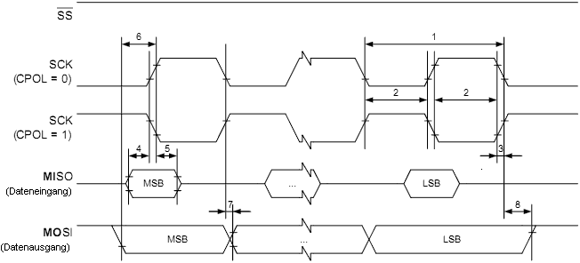
| 1 | SCK-Periodendauer | Master | Siehe Tabelle 19-5 | ns | |||||||||||||||||||||||||||||||||||||||||||||||||||||||||||||||||||||||||
| 2 | SCK high/low | Master | 50 % Tastverhältnis | ||||||||||||||||||||||||||||||||||||||||||||||||||||||||||||||||||||||||||
| 3 | Anstiegs- und Abfallzeit | Master | 3,6 | ||||||||||||||||||||||||||||||||||||||||||||||||||||||||||||||||||||||||||
| 4 | Vorhaltezeit | Master | 10 | ||||||||||||||||||||||||||||||||||||||||||||||||||||||||||||||||||||||||||
| 5 | Nachhaltezeit | Master | 10 | ||||||||||||||||||||||||||||||||||||||||||||||||||||||||||||||||||||||||||
| 6 | Out to SCK | Master | 0,5 • tsck|
| 7 | SCK to out | Master | 10 |
| 8 | SCK to out high | Master | 10 |
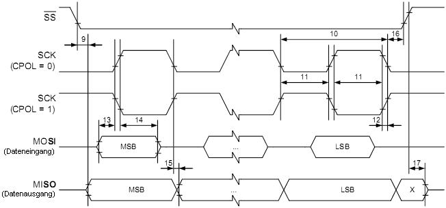
| 9 | SS low to out | Slave | 15 |
| 10 | SCK-Periodendauer | Slave | 4 • tck |
| 11 | SCK high/low(1) | Slave | 2 • tck |
| 12 | Rise/Fall time | Slave | 1600
| 13 | Setup | Slave | 10 |
| 14 | Hold | Slave | tck |
| 15 | SCK to out | Slave | 15 |
| 16 | SCK to SS high | Slave | 20 |
| 17 | SS high to tri-state | Slave | 10 |
| 18 | SS low to SCK | Slave | 20 |
| |


| Symbol | Parameter | Bedingung | Min. | Max. | Einheit | ||||||||||||||||||||||||||||||||||||||||||||||||||||||||||||||||||||||||||||||||||||||||||||||||||||||||||||||||||||||||||||||||||||||||||||||||||||||||
|---|---|---|---|---|---|---|---|---|---|---|---|---|---|---|---|---|---|---|---|---|---|---|---|---|---|---|---|---|---|---|---|---|---|---|---|---|---|---|---|---|---|---|---|---|---|---|---|---|---|---|---|---|---|---|---|---|---|---|---|---|---|---|---|---|---|---|---|---|---|---|---|---|---|---|---|---|---|---|---|---|---|---|---|---|---|---|---|---|---|---|---|---|---|---|---|---|---|---|---|---|---|---|---|---|---|---|---|---|---|---|---|---|---|---|---|---|---|---|---|---|---|---|---|---|---|---|---|---|---|---|---|---|---|---|---|---|---|---|---|---|---|---|---|---|---|---|---|---|---|---|---|---|---|---|---|---|---|
UIL| Input Low-voltage | -0,5 | 0,3 UCC | V
| UIH | Input High-voltage | 0,7 UCC | UCC + 0,5 | V
| Uhys(1) | Hysteresis of Schmitt Trigger Inputs | 0,05 UCC (2) | – | V
| UOL(1) | Output Low-voltage | 3 mA sink current | 0 | 0,4 | V
| tr(1) | Rise Time for both SDA and SCL | 20 + 0,1 Cb(3)(2) | 300 | ns
| tof(1) | Output Fall Time from VIHmin to VILmax | 10 pF < Cb < 400 pF (3) | 20 + 0,1 Cb(3)(2) | 250 | ns
| tSP(1) | Spikes Suppressed by Input Filter | 0 | 50 (2) | ns
| Ii | Input Current each I/O Pin | 0,1 UCC < Vi < 0,9 UCC | -10 | 10 | µA
| Ci(1) | Capacitance for each I/O Pin | – | 10 | pF
| fSCL | SCL Clock Frequency | fCK(4) > max(16 fSCL, 250 kHz) (5) | 0 | 400 | kHz
| Rp | Value of Pull-up resistor
| fSCL ≤ 100 kHz
|
Ω
| fSCL > 100 kHz
|
Ω
| tHD;STA | Hold Time (repeated) START Bedingung
| fSCL ≤ 100 kHz | 4,0 | – | µs
| fSCL > 100 kHz | 0,6 | – | µs
| tLOW | Low Period of the SCL Clock
| fSCL ≤ 100 kHz | 4,7 | – | µs
| fSCL > 100 kHz | 1,3 | – | µs
| tHIGH | High period of the SCL clock
| fSCL ≤ 100 kHz | 4,0 | – | µs
| fSCL > 100 kHz | 0,6 | – | µs
| tSU;STA | Set-up time for a repeated START condition
| fSCL ≤ 100 kHz | 4,7 | – | µs
| fSCL > 100 kHz | 0,6 | – | µs
| tHD;DAT | Data hold time
| fSCL ≤ 100 kHz | 0 | 3,45 | µs
| fSCL > 100 kHz | 0 | 0,9 | µs
| tSU;DAT | Data setup time
| fSCL ≤ 100 kHz | 250 | – | ns
| fSCL > 100 kHz | 100 | – | ns
| tSU;STO | Setup time for STOP condition
| fSCL ≤ 100 kHz | 4,0 | – | µs
| fSCL > 100 kHz | 0,6 | – | µs
| tBUF | Bus free time between a STOP and START condition
| fSCL ≤ 100 kHz | 4,7 | – | µs
| fSCL > 100 kHz | 1,3 | – | µs
| |

| Symbol | Parameter | Bedingung | Min. | Typ. | Max | Einheit | ||||||||||||||||||||||||||||||||||||||||||
|---|---|---|---|---|---|---|---|---|---|---|---|---|---|---|---|---|---|---|---|---|---|---|---|---|---|---|---|---|---|---|---|---|---|---|---|---|---|---|---|---|---|---|---|---|---|---|---|---|
| Auflösung | 10 | Bits | ||||||||||||||||||||||||||||||||||||||||||||||
| Absolute accuracy (Including INL, DNL, quantization error, gain and offset error) | UREF = 4V, VCC = 4V, ADC clock = 200kHz | 2 | LSB | |||||||||||||||||||||||||||||||||||||||||||||
| UREF = 4V, VCC = 4V, ADC clock = 1MHz | 4.5 | LSB | ||||||||||||||||||||||||||||||||||||||||||||||
| UREF = 4V, VCC = 4V, ADC clock = 200kHz Noise Reduction Mode | 2 | LSB | ||||||||||||||||||||||||||||||||||||||||||||||
| UREF = 4V, VCC = 4V, ADC clock = 1MHz Noise Reduction Mode | 4.5 | LSB | ||||||||||||||||||||||||||||||||||||||||||||||
| Integral Non-Linearity (INL) | UREF = 4V, VCC = 4V, ADC clock = 200kHz | 0.5 | LSB | |||||||||||||||||||||||||||||||||||||||||||||
| Differential Non-Linearity (DNL) | UREF = 4V, VCC = 4V, ADC clock = 200kHz | 0.25 | LSB | |||||||||||||||||||||||||||||||||||||||||||||
| Gain Error | UREF = 4V, VCC = 4V, ADC clock = 200kHz | 2 | LSB | |||||||||||||||||||||||||||||||||||||||||||||
| Offset Error | UREF = 4V, VCC = 4V, ADC clock = 200kHz | 2 | LSB | |||||||||||||||||||||||||||||||||||||||||||||
| Conversion Time | Free Running Conversion | 13 | 260 | µs | ||||||||||||||||||||||||||||||||||||||||||||
| Clock Frequency | 50 | 1000 | kHz | |||||||||||||||||||||||||||||||||||||||||||||
AUCC(1)
| Analog Supply Voltage | UCC - 0.3 | UCC + 0.3 | V
| UREF | Reference Voltage | 1.0 | AUCC | V
| UIN | Input Voltage | GND | UREF | V
| Eingangsbandbreite | 38.5 | kHz
| UINT | Internal Voltage Reference | 1.0 | 1.1 | 1.2 | V
| RREF | Reference Input Resistance | 32 | kΩ
| RAIN | Analog Input Resistance | 100 | MΩ
| |
| Symbol | Parameter | Min. | Typ. | Max. | Einheit | ||||||||||||||||||||||||||||||||||||||||||||||||||||||||||||||||||||||||||||||||||||||||||||||||||||||||||||||||||||||||||||||||||||
|---|---|---|---|---|---|---|---|---|---|---|---|---|---|---|---|---|---|---|---|---|---|---|---|---|---|---|---|---|---|---|---|---|---|---|---|---|---|---|---|---|---|---|---|---|---|---|---|---|---|---|---|---|---|---|---|---|---|---|---|---|---|---|---|---|---|---|---|---|---|---|---|---|---|---|---|---|---|---|---|---|---|---|---|---|---|---|---|---|---|---|---|---|---|---|---|---|---|---|---|---|---|---|---|---|---|---|---|---|---|---|---|---|---|---|---|---|---|---|---|---|---|---|---|---|---|---|---|---|---|---|---|---|---|---|---|---|---|
UPP| Spannung zur Programmierfreigabe | 11.5 | 12.5 | V
| IPP | Strom der Programmierfreigabe | 250 | μA
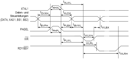
| tDVXH | Vorhaltezeit Daten und Steuersignale vor XTAL1 High | 67 | ns
| tXLXH | Vorhaltezeit XTAL1 Low bis XTAL1 High | 200 | ns
| tXHXL | Pulsbreite XTAL1 High | 150 | ns
| tXLDX | Nachhaltezeit Daten und Steuersignale nach XTAL1 Low | 67 | ns
| tXLWL | Vorhaltezeit XTAL1 Low bis WR Low | 0 | ns
| tXLPH | Vorhaltezeit XTAL1 Low bis PAGEL high | 0 | ns
| tPLXH | Vorhaltezeit PAGEL low bis XTAL1 high | 150 | ns
| tBVPH | Vorhaltezeit BS1 Valid bis PAGEL High | 67 | ns
| tPHPL | Pulsbreite PAGEL High | 150 | ns
| tPLBX | Nachhaltezeit BS1 nach PAGEL Low | 67 | ns
| tWLBX | Nachhaltezeit BS2/1 nach WR Low | 67 | ns
| tPLWL | Vorhaltezeit PAGEL Low bis WR Low | 67 | ns
| tBVWL | Vorhaltezeit BS1 Valid bis WR Low | 67 | ns
| tWLWH | Pulsbreite WR Low | 150 | ns
| tWLRL | Reaktionszeit WR Low bis RDY/BSY Low | 0 | 1 | μs
| tWLRH | Reaktionszeit WR Low bis RDY/BSY High(1) | 3,7 | 4,5 | ms
| tWLRH_CE | Vorhaltezeit WR Low bis RDY/BSY High für Chip Löschen(2) | 7,5 | 9 | ms
| tXLOL | Vorhaltezeit XTAL1 Low bis OE Low | 0 | ns
| tBVDV | Reaktionszeit BS1 gültig bis DATA gültig | 0 | 250 | ns
| tOLDV | Reaktionszeit OE Low bis DATA gültig | 250 | ns
| tOHDZ | Reaktionszeit OE High bis DATA hochohmig | 250 | ns
| |
