There is no Windows function available to control dedicated pins of parallel port, therefore, the only choice for programmers is to directly access the hardware.
Serial ports are very well wrapped by Win32 functions,
and it is very inconvenient for programmers to access a
serial port directly.
The two control lines (RTS and DTR) and the TxD line are easily
controllable using
EscapeCommFunction() function.
The four status lines (CTS, DSR, DCD, RI) and the RxD line can be queried by
GetCommModemStatus() function.
This applies to old 16-bit Windows programs too — the Win16 API is similar.
Some programs are very slow when working with USB to serial converters. For example, simple PIC programmers.
- USB High-Speed: 256000 OUT and 8000 IN instructions per second
- USB Low-Speed (upto XP), Full-Speed: 4000 OUT and 1000 IN instructions per second
- USB Low-Speed (Vista and newer) 500 OUT and 125 IN instructions per second
How many bits per second are transferred using bit-banging depends heavily on your application. For following calculations, I assume USB high-speed.
The obvious limit is 8 kBit/s for read access (e.g. flash verify).
Practically, the limit is roughly the half by Windows's driver design.
If write access is written with USB2LPT or any other redirection in mind, it's still much faster.
However, most apps check each clock and data bit they write, so the speed drops
by factor 4 (even for write-only access), so we reach 1 kBit/s.
Even worse for JTAG because there are two data-out lines that are often checked
independently. So it drops to 600 bit/s.
Often, software re-reads every written byte, to be extra sure, this halfs the data rate again.
Therefore, expect no more than 0,5 .. 1 kBit/s transfer rates.
For example: avrdude (a popular command-line-driven Atmel AVR programmer software)
needs 18 seconds to read an ATmega16 via parallel port. That is 7 kBit/s. Not very fast, but sufficient.
With USB2LPT, it needs 6 minutes, that is 0,5 kBit/s.
A good AVR project for those (larger) controllers have a bootloader,
which is much faster and more convenient than programming via parallel port,
so you often need USB2LPT only for “doping” the typical 1 KByte bootloader
(which takes affordable 20 seconds via USB2LPT),
or for some troubleshooting (and — in case of AVR — setting fuses).
Specialized software aware to USB2LPT (i.e. that uses the USB2LPT API) can be much faster, up to roughly 20 MByte/s, by replacing parts of the firmware in controller's RAM on-the-fly.
Limitations for instant help may occur. You should install the .rtf-based .hlp file package from Microsoft:
- Windows Help program (WinHlp32.exe) for Windows Vista
- Windows Help program (WinHlp32.exe) for Windows 7
- Windows Help program (WinHlp32.exe) for Windows 8
While there is a 64 bit driver available, it does not feature the debug register redirection. Furthermore, the well-worked READ/WRITE_PORT_UCHAR redirection cannot work. There are simply no kernel functions to trap. However, the property sheet and the API is fully functional, so you can access the port pins with specialized software, e.g. my special build of inpout32.dll.
You may have luck especially for some older software (last update before 1995), you can check whether you can record IN & OUT instructions with this Dongle Emulator. Note that this program runs on Windows 3.1, 3.11, 95, 98, Me and 2000, but not on XP and newer (it seems to work but it doesn't record anything), whereas USB2LPT works on newer systems too.
 No, USB2LPT is not perfect, however, suitable. The disadvantages are:
- relatively unstable operation due to hardcore driver programming
- currently not portable to non-Windows systems
- driver installation necessary on target systems (it's annoying to most users)
- USB2LPT is not in mass production, it's hand-made in low counts
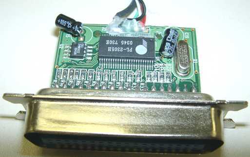
For up to 3 output lines (and up to 5 input lines) it's quite perfect to use a serial port. USB→Serial adapters like this work seamlessly and — in many cases — fast enough. But note that mostly you have convert output voltages to TTL levels; for example with zener diodes 3.9 V. The maximum data rate via USB is 1000 level transitions per second.
For up to 8 output lines and 3 input lines,
I recommend using a regular and cheap USB→Printer adapter, like
this or
this.
However, the 5 V USB supply voltage is not available.
The connection requires some circuitry.
Read this detailed article
for possible solutions.
The maximum data rate is about 100000 level transitions per second
(even at multiple lines the same time, that's reasonably fast!),
so it's perfect for controlling LEDs
– or alphanumeric LC display controllers in nibble mode
– or pixel graphics LC display controllers in serial mode or using a port expander.
Many devices don't need inputs, e.g. stepper motors, serial D/A converters,
or DDS frequency generators often used in ham radio applications.
The status lines ERR ⑮, ONL ⑬, and PE ⑫ can be read using
DeviceIoControl(…,IOCTL_USBPRINT_GET_LPT_STATUS,…)
with 1 kByte/s maximum speed.
The INIT (16) line can only be controlled to output a LOW spike of some µs, nothing else, using
DeviceIoControl(…,IOCTL_USBPRINT_SOFT_RESET,…).
The remaining control and status lines STB ①,
AF ⑭, SEL (17), ACK ⑩, and BUSY ⑪
are definitively not useable!
You get a handle to the USB→Printer adapter using
this weird Win32-API code.
It's much easier for Linux, simply open /dev/usb/lpn.
Unlimited output lines can be achieved using port expander circuits like 74HCT595, either attached to any parallel or serial port solution stated above.
For output and input lines and USB power (and built-in “brain”) you should use HID-based solutions like this or this or this.
For up to 2 (possibly also 6) output lines with precise timing control in microseconds
pick your … sound card!!
You have to solve DC clamping and amplification yourself,
use operational amplifiers, comparators, possibly diodes and analog switches for this.
The Win32 workhorse function for waveform output is
waveOutWrite().
- For stepper drives, especially for tool machines, I disencourage systems that use a parallel port to put DIR and STEP instructions to the motors. Because microstepping is state-of-the-art since 20 years. In the microstepping world, you think in coil currents, phase angles or Bresenham's microstep widths at constant rate instead of in steps. Refer to the modern Trinamic motor controller TMC249!
- Motor controllers that except step frequencies above 10 kHz are generally microstep controllers that convert the steps in coil currents. Therefore, generating high step frequencies is a “detour” in terms of information technology.
- For transferring microstep widths with constant sampling rate
(e.g. 10 kHz) via USB, there is luckily a USB class, the
Audio Device Class,
that matches this application very well.
Using this standard USB class imposes superior advantages for future CNC tool machines:
- One 8-bit “audio” channel per motor transferring the microsteps to do, very compact, easy and comprehensible operation
In opposite to audio-PCM, where positions (of speaker membrane) are transferred, speed values (= differentials of positions) are transferred here. For 8-bit data channels I suggest using signed char values of –64 (full step back) to +64 (full step forward) — accidental audio data is 80h centered and will render as invalid data automatically. - Cheaper and widely available USB full-speed controllers are fully sufficient
- Good balancing of computational work between PC and USB device
- Buffering of data stream handled by built-in audio subsystem, no “interrupt frequency” of PC software necessary
- No specialized USB kernel-mode driver necessary, runs with 32 and 64 bit versions of Windows, Linux, and MacOS
- Low overhead of USB sound driver using isochronous transfers, low latency when using DirectSound
- Zero phase difference between multiple channels
- “Back Channel” (i.e. Audio Input) for motor/endswitch error/status or encoder data reporting easily available
- Full free-form numeric-controlled trajectories (more than G-code with its lines and arcs, like splines, evolventes, evolutes, etc.), simply recordable in well-known and reasonably compact .WAV files
- CNC machine is testable with any .WAV file player and such .WAV files (if player supports the required channel count)
- Very suitable for parallel kinematics (e.g. hexapods), the controller may transform linear axes to motor axes if NC software doesn't supports this
- Automatic sleep mode with reduced power consumption of CNC machine while not streaming “audio” data
- One 8-bit “audio” channel per motor transferring the microsteps to do, very compact, easy and comprehensible operation
For the USB Microcontroller, IMHO, ARM7 based controllers are best suited, like
NXP (former Philips)
LPC214x
or Atmel
AT91SAM7S
or
AT32UC3B64 too.
The brand-new MSP430F55xx
by Texas Instruments
are not suited due to missing isochronous USB Pipes.
I will pick up this problem when I gather a CNC tool machine.
 For controlling
LCD,
someone recommends USB2LPT. Is this OK?
For controlling
LCD,
someone recommends USB2LPT. Is this OK?
- Low-Speed (Version 1.6) is sufficient for text-only LCD
(See picture; for monitoring line levels,
 LPT Checker is used here)
- For raster-graphics LCD, the speed advantage of USB2LPT High-Speed (1.7) is very noticeable
- An extra advantage is the availability of 5 V at Pin 25 of D-Sub connector
However, there are some issues to point to before deciding to use USB2LPT:
- For LED and LCD (Seven-Segment, 14-Segment, Dot Matrix and raster-graphics) there is a Usage Page of the well-known USB HID device class! See HID Usage Tables 1.12, from page 109 „18 Alphanumeric Display Page (0x14)“ downwards. This specification exists to be used. Not to re-invent the wheel over and over again.
- Well-made control software can enumerate number, size and capabilities of all such displays in a system. True PnP at its best.
- A reference implementation ist currently under construction. To make USB2LPT useless (really!). On the other hand, to make communication to raster-graphics displays pretty fast, even using USB Low-Speed and V-USB.
- However I don't know suitable PnP-capable control software. There are so many “unemployed” programmers around, can someone else improve the dozens of those programs (LCDhype, LCDinfo etc.)?
Hobbyists who are fraud programming microcontrollers should give USB→Printer adapters (see above) a try. Advantages:
- No speed problem
- No acquisition problem (of those adapters)
- Easily comprehensive schematic with SSI (gates) and MSI (flip-flops) only
It's a good idea to route Enable through an inverter gate from STB! This should avoid the need for the flip-flops (74HCT574) as line-level catchers. For some display controllers, even the inverter is not necessary.
Note by JGrosJean at ieee.org: “My low speed USB2LPT works in WinXP running on a virtual machine using Oracle VirtualBox in Linux.”
Maybe there is a backdoor (undocumented features to access the pins directly), but that's hard to find out, if any available.
The PL-2305 has a backdoor. Its descriptor is as follows:The »Alternate Setting Nr. 2« had no function. Probably, this is a IEEE 1284.4 protocol stub.
- Device (string descriptors can be defined in EEPROM), Class »Multifunction«
- Configuration Nr. 1
- Interface Nr. 0
- Alternate Setting Nr. 0
Class: 07/01 = Drucker, Protocol: 01 = one direction
- Endpoint Nr. 2, Bulk, Output, 64 Bytes
- Alternate Setting Nr. 1
Class: 07/01 = Drucker, Protocol: 02 = two directions
- Endpoint Nr. 1, Bulk, Output, 64 Bytes
- Endpoint Nr. 2, Bulk, Input, 64 Bytes
- Alternate Setting Nr. 2
Class: FF/00 = gusto, Protocol: FF = gusto
- Endpoint Nr. 1, Bulk, Output, 64 Bytes
- Endpoint Nr. 2, Bulk, Input, 64 Bytes
- Endpoint Nr. 3, Interrupt, 4 Bytes, Interval: 1 ms
On the other hand, it's easy to speed up REP INSB instructions. But these are seldom used in conjunction with ECP/EPP ports. With a standard parallel port, REP INSB is completely useless and therefore never used.
Each instruction consumes about 1 µs. Delayed operation can be achieved using WAIT instructions (20h, thereafter the delay time in units of 4 µs) in the OUT packet. Slower delays you should achieve in software.
This converter (until Revision 1.1) has the following descriptor:Such a two-interface device forms two devices. For this, Windows loads a “fork” driver, that itself loads two real drivers.
- Device "USB2LPT Converter", Class »Multifunction«
- Configuration Nr. 1
- Interface Nr. 0
- Alternate Setting Nr. 0
Class: FF/FF = gusto, Protocol: FF = gusto
- Endpoint Nr. 2, Bulk, Output, 64 Bytes
- Endpoint Nr. 2, Bulk, Input, 64 Bytes
- Interface Nr. 1
- Alternate Setting Nr. 0
Class: 07/01 = Printer, Protocol: 01 = one direction
- Endpoint Nr. 4, Bulk, Output, 64 Bytes
- Alternate Setting Nr. 1
Class: 07/01 = Printer, Protocol: 02 = two directions
- Endpoint Nr. 4, Bulk, Output, 64 Bytes
- Endpoint Nr. 4, Bulk, Input, 64 Bytes
For more exact timing I advise you to “roll your own” and write your own 8051 program. You can download it anytime to the converter. [This converter is actually almost the same as an EZ-USB development board!]
usb2lpt.inf file to include the following sections:
This example sets the base address to 278h, timeout to 200 ms, and mode = ECP + EPP.[Dev.ntx86.HW] AddReg = usercfg_addreg [usercfg_addreg] HKR,,UserCfg,1,78,02,c8,00,06,03
The number 1 after UserCfg declares following data as hex-binary. The data structure for these bytes has the following content (see source file
usb2lpt.h):
struct USERCFG {
 USHORT LptBase; // trapped base address (EPP = base address + 4, ECP = base address + 0x400)
 USHORT TimeOut; // timeout value for write-back cache (both little-endian values)
 UCHAR flags;	 // OR-ed values of the following bits
#define UC_Debugreg	0x01	// Use debug register trap (one of four debug registers for every address range)
#define UC_Function	0x02	// Redirect kernel-mode access routines (READ_PORT_UCHAR etc.)
#define UC_WriteCache	0x04	// Enable write-back cache
#define UC_ReadCache0	0x08	// Enable read-ahead for base address+0
#define UC_ReadCache2	0x10	// Enable read-ahead for base address+2
#define UC_ReadCacheN	0x20	// Enable read-ahead for other registers (without effect)
#define UC_ForceRes	0x40	// unused
#define UC_ForceDebReg	0x80	// Force debug register usage even if used previously (Win98 problem)
 UCHAR Mode;	 // enum SPP,EPP,ECP,EPP+ECP
};
A complete PCB redesign would be necessary: Not worth at all while cheap “gender changers” are available.
Every i86 and AMD64 compatible processor has four debug register sets. In case of SMP machines, this number remains the same because all processors must be programmed to halt on the same breakpoints (to be symmetrically). Indeed, the driver contains instructions to run specific code on one specific processor, that is scheduled in a small loop for all processors while the “main” (the calling) processor waits for completion of the others. It was somehow tricky but it works. There is no Windows Kernel API for doing this, but some API for helping: A deferred procedure call (DPC) with a hint to run on a specific processor. The current code doesn't support hot-swapping of processors, I have no machine to test this:-)
The USB2LPT.SYS driver consumes 1..3 debug register sets
for each USB2LPT device, depending on emulation mode.
For SPP mode
(which is by far most-often sufficient),
the minimum of 1 set covers all the 3 adjanced addresses,
e.g. 0x378..0x37A.
(To be true, it will cover 4 addresses,
but the driver silently ignores the fourth address e.g. 0x37B.)
So, when using SPP only, four USB2LPT devices can be connected to one PC with hardware virtualization using debug register trapping method.
The driver itself currently limits devices to nine (not to have LPT10 or more).
But the fifth device will not acquire debug register trap virtualization.
The other type of virtualization, READ/WRITE_PORT_UCHAR/USHORT/ULONG,
will be in effect for unlimited USB2LPT devices,
so if you know your different accessing software a bit,
you can assign redirection method to specific addresses and hence to specific applications.
For Windows 9x/Me, this applies to the IOPM trap too.
For AMD64 versions, unluckily, no READ/WRITE_PORT_UCHAR/USHORT/ULONG API exists,
so only the debug register trap can ever work, but that's still hard to implement.
Because there is driver certification enforcement in effect,
there is only a handful of drivers available accessing port addresses.
The well-known INPOUT32.DLL
(or INPOUTX64.DLL) contains such certified drivers.
The DLL code silently installs and loads (and unloads) that driver
when the DLL is loaded or unloaded.
So it's easy to make a replacement INPOUT32.DLL that “speaks” to USB2LPT device
through its native interface, not needing any quirks like debug register trap.