)
The Windows Driver Model formalizes a layering of drivers, as illustrated in FigureĀ2-1. A stack of device objects appears at the left of the figure. The device objects are data structures that the system creates to help software manage hardware. Many of these data structures can exist for a single piece of physical hardware. The lowest-level device object in a stack is called the physical device object, or PDO for short. Somewhere in the middle of a device object stack is an object called the functional device object, or FDO. Above and below the FDO there might be a collection of filter device objects. Filter device objects above the FDO are called upper filters, whereas filter device objects below the FDO (but still above the PDO) are called lower filters.
Figure 2-1. Layering of device objects and drivers in the WDM.
The Plug and Play (PnP) Manager component of the operating system constructs the stack of device objects at the behest of device drivers. For our purposes in this book, we can use the generic term bus to describe a piece of hardware to which devices connect electronically. This is a pretty broad definition. Not only does it include things like the PCI (Peripheral Component Interconnect) bus, but it also includes a SCSI (Small Computer System Interface) adapter, a parallel port, a serial port, a USB (universal serial bus) hub, and so on—anything, in fact, that can have multiple devices plugged into it. One responsibility of the driver for a bus is to enumerate the devices attached to the bus and to create PDOs for each of them. The PnP Manager begins painting the picture in Figure 2-1, then, by creating a PDO because some bus driver has detected some actual hardware.
Having created a PDO, the PnP Manager consults the registry database to find the filter and function drivers that occupy the middle of the figure. The setup program is responsible for many of these registry entries, and the INF files that control hardware installation are responsible for others. The registry entries define the order in which the drivers will appear in the stack, so the PnP Manager begins by loading the lowest-level filter driver and calling its AddDevice function. This function creates a FiDO, thus establishing the horizontal link between a FiDO and a driver. AddDevice then connects the PDO to the FiDO; that's where the line connecting the two device objects comes from. The PnP Manager proceeds upward, loading and calling each lower filter, the function driver, and each upper filter, until the stack is complete.
The purpose for the layering becomes apparent when you consider the flow of I/O requests diagrammed on the right-hand side of Figure 2-1. Each request for an operation affecting a device uses an I/O request packet (IRP). IRPs are normally sent to the topmost driver for the device and can percolate down the stack to the other drivers. At each level, the driver decides what to do with the IRP. Sometimes, a driver will do nothing except pass the IRP down. Other times, a driver might completely handle the IRP without passing it down. Still other times, a driver might process the IRP and pass it down, or vice versa. It all depends on the device and the exact semantics of the IRP. I'll explain in a later sidebar how it comes to pass that drivers can send IRPs down even though device objects are linked upward from the PDO.
The various drivers that occupy the stack for a single piece of hardware perform different roles. The function driver manages the device, represented by the FDO. The bus driver manages the connection between the device and the computer, represented by the PDO. Because of the close relationship between driver software and device object, I'll sometimes use the term FDO driver to mean the function driver and the term PDO driver to refer to the bus driver. The filter drivers, if they even exist, monitor or modify the stream of IRPs.
One of my seminar students, on seeing a diagram similar to Figure 2-1, was misled (I won't say by which teacher, who also wrote this book) into thinking of C++ and class inheritance. A perfectly reasonable way of designing an architecture for device drivers would be to define base classes from which programmers could derive progressively more specialized classes. In such a scheme, you could have a set of abstract classes that manage different sorts of PDOs, and you could derive FDO drivers from them. The system would send IRPs to virtual functions, some of which would be handled by the base class in the PDO driver and some of which would be handled by the derived class in the FDO driver. WDM doesn't work this way, though. The PDO driver performs completely different jobs from the FDO driver. The FDO driver "delegates" certain work to the PDO driver by passing IRPs down to it, but the relationship is more like being peers in a bucket brigade (and we won't discuss the contents of the metaphorical buckets!) than like being hierarchically related.
Having presented this much description of device layering in the WDM, it's time for me to be a bit more precise. To begin with, there's an obvious chicken-and-egg problem with what I've described. I said that the bus driver creates the PDO, but I also said that the PnP Manager loads drivers based on registry entries for a PDO that already exists. So where does the bus driver come from? I'll explain that in the next section. The registry database plays a crucial role in the process of loading drivers and configuring devices, so I'll explain which registry keys are relevant and what they contain.
In the first instance, the PnP Manager has a built-in "driver" for a "root" bus that doesn't actually exist. The root bus conceptually connects the computer to all hardware that can't electronically announce its presence—including the primary hardware bus (such as PCI). The root bus driver gets information about the computer from the registry, which was initialized by the Windows 2000 Setup program. Setup got the information by running an elaborate hardware detection program and by asking the end user suitable questions. Consequently, the root bus driver knows enough to create a PDO for the primary bus.
The function driver for the primary bus can then enumerate its own hardware electronically. The PCI bus, for example, provides a way of accessing a special configuration space for each attached device, and the configuration space contains a description of the device and its resource requirements. When a bus driver enumerates hardware, it acts in the guise of an ordinary function driver. Having detected a piece of hardware, however, the driver switches roles: it becomes a bus driver and creates a new PDO for the detected hardware. The PnP Manager then loads drivers for this device PDO, as previously discussed. It might happen that the function driver for the device enumerates still more hardware, in which case the whole process repeats recursively. The end result will be a tree like that shown in Figure 2-2, wherein a bus device stack branches into other device stacks for the hardware attached to that bus.
)
Figure 2-2. Layering of recursively enumerated devices.
Three different registry keys bear on configuration. These are called the hardware key, the class key, and the service key. To be clear, these are not the proper names of specific subkeys: they are generic names of three keys whose pathnames depend on the device to which they belong. Broadly speaking, the hardware key contains information about a single device, the class key concerns all devices of the same type, and the service keys contains information about drivers. People sometimes use the name "instance key" to refer to the hardware key and "software key" to refer to the service key. The multiplicity of names derives from the fact that Windows 95/98 and Windows 2000 were written (mostly) by different people.
The Hardware (Instance) Keys Device hardware keys appear in the \System\CurrentControlSet\Enum subkey of the local machine branch of the registry. You normally can't look inside this key because the system grants access to the System account only. In other words, kernel-mode programs and user-mode services running in the System account can read from and write to the Enum key and its subkeys, but not even an administrator can do so. To see what's inside Enum, you can run REGEDT32.EXE from an administrator-privilege account and change the security settings. Figure 2-3 illustrates the hardware key for one of the sample devices that accompanies this book (namely, the USB42 sample I'll discuss in Chapter 11, "The Universal Serial Bus").
)
Figure 2-3. A hardware key in the registry.
The subkeys on the first level below the Enum key correspond to the different bus enumerators in the system. The description of all past or present USB devices is in the …\Enum\USB subkey. I've expanded the key for the USB42 sample to show you how the device's hardware ID (vendor 0574, product 102A) has turned into the name of a key (Vid_0547&Pid_102A) and how a particular instance of the device that has that ID appears as a further subkey named 7&2. The 7&2 key is the hardware, or instance, key for this device.
Some of the values in the hardware key provide descriptive information that user-mode components such as the Device Manager can use. (You reach the Device Manager from the Management Console or, more easily, from the Hardware tab of the property sheet you get when you right-click the My Computer desktop icon and select Properties.) Figure 2-4 shows how the Device Manager portrays the properties of USB42. Refer to the sidebar "Accessing Device Keys from User Mode" for an indication of how the Device Manager can gather this information even though it can't, by itself, get past the normal security block to the Enum key.
)
Figure 2-4. The Device Manager properties display for a device.
The hardware key also contains several values that identify the class of device to which the device belongs and the drivers for the device. ClassGUID is the ASCII representation of a globally unique identifier (GUID) that uniquely identifies a device class; in effect, it's a pointer to the class key for this device. Service is a pointer to the service key. Optional values (which USB42 doesn't have) named LowerFilters and UpperFilters, if present, would identify the service names for any lower or upper filter drivers, respectively.
Finally, a hardware key might have overriding values named Security, Exclusive, DeviceType, and DeviceCharacteristics that force the device object the driver will create to have certain attributes. I'll discuss the importance of these overrides later on when I tell you how to create a device object.
Most of the values in the hardware key get there automatically as part of the setup process or because the system recognizes new hardware (or gets told it about via the Hardware Wizard) sometime after initial setup. Some of the values get there because the INF file that's used to install the hardware directs that they be put there. I'll discuss INF files when I talk about how to plan for installation in Chapter 12, "Installing Device Drivers."
The Class Keys The class keys for all classes of device appear in the HKLM\System\CurrentControlSet\Control\Class key. Their key names are GUIDs assigned by Microsoft. Figure 2-5 illustrates the class key for SAMPLE devices, which is the class to which the USB42 sample and all the other sample drivers in this book belong.
)
Figure 2-5. A class key in the registry.
The USB class isn't particularly interesting as it lacks some of the optional values that might be there, such as these:
Each device also has its own subkey below the class key. The name of this key is the Driver value in the device's hardware key. Refer to Figure 2-6 for an illustration of the contents of this subkey, the purpose of which is to correlate all these registry entries with the INF file used to install the device.
)
Figure 2-6. A device-specific subkey of the device's class key in the registry.
The Service (Software) Keys The last key that's important for a device driver is the service key. It indicates where the driver's executable file is on disk and contains some other parameters that govern the way the driver is loaded. Service keys appear in the HKLM\System\CurrentControlSet\Services key. Refer to Figure 2-7 for USB42's service key.
)
Figure 2-7. A service key in the registry.
It's not my purpose to rehash all the possible settings in the service key, which is splendidly documented in several places, including under the heading "Service Install" in the Platform Software Development Kit (SDK). In this particular case, the values have the following significance:
When the PnP Manager encounters a new device, it opens the hardware and class keys and proceeds to load drivers in the following order:
When I say the system "loads" a driver, I mean that it maps the driver's image into virtual memory, fixes up relocatable references, and calls the driver's main entry point. The main entry point is usually named DriverEntry. I'll describe the DriverEntry function a bit further on in this chapter. It might turn out that a particular driver is already present in memory, in which case nothing happens at the load stage except incrementing a reference count that will preserve the image in memory for however long some device needs it.
You might have noticed that the loading of upper and lower filters belonging to the class and to the device instance isn't neatly nested as you might have expected. Before I knew the facts, I guessed that device-level filters would be closer to the function driver than class-level filters. As we'll see later on, it's not very important in what order the loading occurs. However, the system calls the drivers' AddDevice functions (another topic I'll discuss in considerable detail shortly) in the same order in which the PnP Manager loads the drivers. Consequently, the device object stack will mirror this order, with possibly unexpected results.
The tree of device object stacks shown in Figure 2-2 doesn't imply that IRPs necessarily flow from a PDO to the top FiDO for the next lower branch of the tree. In fact, the driver for one stack's PDO is the FDO driver for the next lower branch, as illustrated by the shading in the figure. When the driver receives an IRP in its PDO role, it will do something to perform the IRP, but that might not involve sending the same, or even any other, IRP to the devices in the stack it occupies while performing its FDO role. Conversely, when a bus driver receives an IRP in its FDO role, it might or might not need to send some IRPs to one or more of the devices for which it acts as PDO.
A few examples should clarify the relationship between FiDOs, FDOs, and PDOs. The first example concerns a read operation directed to a device that happens to be on a secondary PCI bus that itself attaches to the main bus through a PCI-to-PCI bridge chip. To keep things simple, let's suppose that there's one FiDO for this device, as illustrated in Figure 2-8. You'll learn in later chapters that a read request turns into an IRP with a major function code of IRP_MJ_READ. Such a request would flow first to the upper FiDO and then to the function driver for the device. (That driver is the one for the device object marked FDOdev in the figure.) The function driver calls the hardware abstraction layer (HAL) directly to perform its work, so none of the other drivers in the figure will see the IRP.
)
Figure 2-8. The flow of a read request for a device on a secondary bus.
A variation on the first example is shown in Figure 2-9. Here we have a read request for a device plugged into a USB hub that itself is plugged into the host controller. The complete device tree therefore contains stacks for the device, for the hub, and for the host controller. The IRP_MJ_READ flows through the FiDO to the function driver, which then sends one or more IRPs of a different kind downward to its own PDO. The PDO driver for a USB device is USBHUB.SYS, and it forwards the IRPs to the topmost driver in the host controller device stack, skipping the two-driver stack for the USB hub in the middle of the figure.
)
Figure 2-9. The flow of a read request for a USB device.
The third example is similar to the first, except that the IRP in question is a notification concerning whether a disk drive on a PCI bus will or will not be used as the repository for a system paging file. You'll learn in Chapter 6, "Plug and Play," that this notification takes the form of an IRP_MJ_PNP request with the minor function code IRP_MN_DEVICE_USAGE_NOTIFICATION. In this case, the FiDO driver will pass the request to the FDOdev driver, which will take note of it and pass it further down the stack to the PDOdev driver. This particular notification has implications about how other I/O requests that concern the PnP system or power management will be handled, so the PDOdev driver sends an identical notification to the stack within which it's the FDObus, as illustrated in Figure 2-10. (Not all bus drivers work this way, but the PCI bus does.)
)
Figure 2-10. The flow of a device usage notification.
To better visualize the way device objects and drivers are layered, it helps to have a tool. I wrote the DEVVIEW utility, which you'll find on the companion disc, for this purpose. I'll be describing other uses for DEVVIEW in this chapter, but the feature that concerns us now is its ability to display the device objects that are used to manage hardware devices. With the so-called Answer device plugged into my USB hub, I ran DEVVIEW and generated the two screen shots shown in Figure 2-11 and Figure 2-12.
This particular device uses only two device objects. The PDO is managed by USBHUB.SYS, whereas the FDO is managed by USB42.SYS (the image for the Answer device). In the first of these screen shots, you can see other information about the PDO. Based on our exploration of the registry keys associated with USB42, it should now be clear where that information came from.
It's worth experimenting with DEVVIEW on your own system to see how various drivers are layered for the hardware you own.
)
Figure 2-11. DEVVIEW information about USB42's PDO.
)
Figure 2-12. DEVVIEW information about USB42's FDO.
The I/O Manager uses a driver object data structure to represent each device driver. See Figure 2-13. Like many of the data structures we'll be discussing, the driver object is partially opaque. This means that you and I are only supposed to directly access or change certain fields in the structure, even though the DDK headers declare the entire structure. I've shown the opaque fields of the driver object in the figure with a gray background. These opaque fields are analogous to the private and protected members of a C++ class, and the accessible fields are analogous to public members.
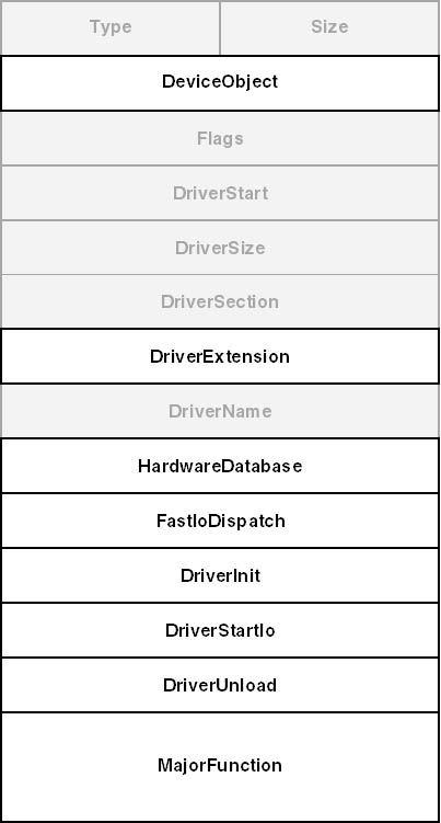
Figure 2-13. The DRIVER_OBJECT data structure.
The DDK headers declare the driver object, and all other kernel-mode data structures for that matter, in a stylized way, as this excerpt from WDM.H illustrates:
typedefĀstructĀ_DRIVER_OBJECTĀ{
ĀĀCSHORTĀType;
ĀĀCSHORTĀSize;
ĀĀ...
ĀĀ}ĀDRIVER_OBJECT,Ā*PDRIVER_OBJECT;
|
That is, the header declares a structure with a type name of DRIVER_OBJECT. It also declares a pointer type (PDRIVER_OBJECT) and assigns a structure tag (_DRIVER_OBJECT). This declaration pattern appears many places in the DDK, and I won't mention it again. The headers also declare a small set of type names (like CSHORT) to describe the atomic data types used in kernel mode. Table 2-1 lists some of these names. CSHORT, for example, means "signed short integer used as a cardinal number."
Table 2-1. Common type names for kernel-mode drivers.
| Type Name | Description |
|---|---|
| PVOID, PVOID64 | Generic pointers (default precision and 64-bit precision) |
| NTAPI | Used with service function declarations to force use of _ _stdcall calling convention on x86 architectures |
| VOID | Equivalent to "void" |
| CHAR, PCHAR | 8-bit character, pointer to same (signed or not according to compiler default) |
| UCHAR, PUCHAR | Unsigned 8-bit character, pointer to same |
| SCHAR, PSCHAR | Signed 8-bit character, pointer to same |
| SHORT, PSHORT | Signed 16-bit integer, pointer to same |
| USHORT, PUSHORT | Unsigned 16-bit integer, pointer to same |
| LONG, PLONG | Signed 32-bit integer, pointer to same |
| ULONG, PULONG | Unsigned 32-bit integer, pointer to same |
| WCHAR, PWSTR | Wide (Unicode) character or string |
| PCWSTR | Pointer to constant Unicode string |
| NTSTATUS | Status code (typed as signed long integer) |
| LARGE_INTEGER | Signed 64-bit integer |
| ULARGE_INTEGER | Unsigned 64-bit integer |
| PSZ, PCSZ | Pointer to ASCIIZ (single-byte) string or constant string |
| BOOLEAN, PBOOLEAN | TRUE or FALSE (equivalent to UCHAR) |
I'll briefly discuss the accessible fields of the driver object structure now.
DeviceObject (PDEVICE_OBJECT) anchors a list of device object data structures, one for each of the devices managed by the driver. The I/O Manager links the device objects together and maintains this field. The DriverUnload function of a non-WDM driver would use this field to traverse the list of device objects in order to delete them. A WDM driver probably doesn't have any particular need to use this field.
DriverExtension (PDRIVER_EXTENSION) points to a small substructure within which only the AddDevice (PDRIVER_ADD_DEVICE) member is accessible to the likes of us. (See Figure 2-14.) AddDevice is a pointer to a function within the driver that creates device objects; this function is rather a big deal, and I'll discuss it at length later in this chapter.
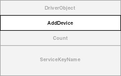
Figure 2-14. The DRIVER_EXTENSION data structure.
HardwareDatabase (PUNICODE_STRING) describes a string that names a hardware database registry key for the device. This is a name like "\Registry\Machine\Hardware\Description\System" and names the registry key within which resource allocation information resides. WDM drivers have no need to access the information below this key because the PnP Manager performs resource allocation automatically. The name is stored in Unicode. (In fact, all kernel-mode string data uses Unicode.) I'll discuss the format and the use of the UNICODE_STRING data structure in the next chapter.
FastIoDispatch (PFAST_IO_DISPATCH) points to a table of function pointers that file system and network drivers export. How these functions are used is beyond the scope of this book. If you're interested in learning more about file system drivers, consult Rajeev Nagar's Windows NT File System Internals: A Developer's Guide (O'Reilly & Associates, 1997).
DriverStartIo (PDRIVER_STARTIO) points to a function in your driver that processes I/O requests that the I/O Manager has serialized for you. I'll discuss request queuing in general and the use of this routine in particular in Chapter 5, "The I/O RequestPacket."
DriverUnload (PDRIVER_UNLOAD) points to a cleanup function in your driver. I'll discuss this function a bit further on in connection with DriverEntry, but you might as well know now that a WDM driver probably doesn't have any significant cleanup to do anyway.
MajorFunction (array of PDRIVER_DISPATCH) is a table of pointers to functions in your driver that handle each of the roughly two dozen types of I/O request. This table is also something of a big deal, as you might guess, because it defines how I/O requests make it into your code.
Figure 2-15 illustrates the format of a device object and uses the same shading convention for opaque fields that I used in the preceding discussion of driver objects. As the author of a WDM driver, you will create some of these objects by calling IoCreateDevice, but the I/O Manager will be responsible for managing them.
DriverObject (PDRIVER_OBJECT) points to the object describing the driver associated with this device object, usually the one that called IoCreateDevice to create it. Filter drivers sometimes need to use this pointer to find the driver object for a device they're filtering so that they can inspect entries in the MajorFunction table.
NextDevice (PDEVICE_OBJECT) points to the next device object that belongs to the same driver as this one. This field is the one that links device objects together starting from the driver object's DeviceObject member. There's probably no reason for a WDM driver to use this field.
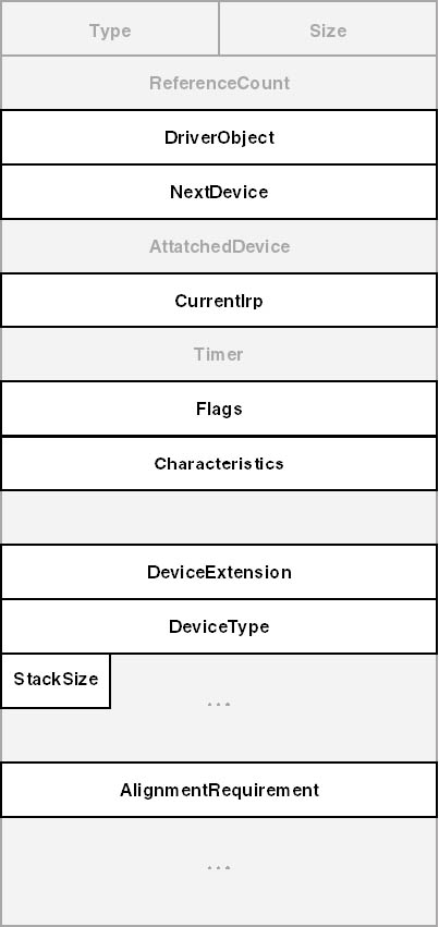
Figure 2-15. The DEVICE_OBJECT data structure.
CurrentIrp (PIRP) points to the I/O request packet most recently sent to the corresponding driver's StartIo function. I'll have more to say about the CurrentIrp field in Chapter 5 when I discuss cancel routines.
Flags (ULONG) contains a collection of flag bits. Table 2-2 lists the bits that are accessible to driver writers.
Table 2-2. Accessible flags in a DEVICE_OBJECT data structure.
| Flag | Description |
|---|---|
| DO_BUFFERED_IO | Reads and writes use the buffered method (system copy buffer) for accessing user-mode data |
| DO_EXCLUSIVE | Only one thread at a time allowed to open a handle |
| DO_DIRECT_IO | Reads and writes use the direct method (memory descriptor list) for accessing user-mode data |
| DO_DEVICE_INITIALIZING | Device object not initialized yet |
| DO_POWER_PAGABLE | IRP_MJ_PNP must be handled at PASSIVE_LEVEL |
| DO_POWER_INRUSH | Device requires large in-rush of current during power-on |
| DO_POWER_NOOP | Device doesn't participate in power management |
Characteristics (ULONG) is another collection of flag bits describing various optional characteristics of the device. (See Table 2-3.) The I/O Manager initializes these flags based on an argument to IoCreateDevice. Filter drivers propagate them upward in the device stack.
Table 2-3. Characteristics flags in a DEVICE_OBJECT data structure.
| Flag | Description |
|---|---|
| FILE_REMOVABLE_MEDIA | Media can be removed from device |
| FILE_READ_ONLY_DEVICE | Media can only be read, not written |
| FILE_FLOPPY_DISKETTE | Device is a floppy disk drive |
| FILE_WRITE_ONCE_MEDIA | Media can be written once |
| FILE_REMOTE_DEVICE | Device accessible through network connection |
| FILE_DEVICE_IS_MOUNTED | Physical media is present in device |
| FILE_DEVICE_SECURE_OPEN | Check security on device object during open operations |
DeviceExtension (PVOID) points to a data structure you define that will hold per-instance information about the device. The I/O Manager allocates space for the structure, but its name and contents are entirely up to you. A common convention is to declare a structure with the type name DEVICE_EXTENSION. To access it given a pointer (for example, fdo ) to the device object, use a statement like this one:
PDEVICE_EXTENSIONĀpdxĀ=Ā(PDEVICE_EXTENSION)Āfdo->DeviceExtension; |
It happens to be true (now, anyway) that the device extension immediately follows the device object in memory. It would be a bad idea to rely on this always being true, though, especially when the documented method of following the DeviceExtension pointer will always work.
DeviceType (DEVICE_TYPE) is an enumeration constant describing what type of device this is. The I/O Manager initializes this member based on an argument to IoCreateDevice. Filter drivers might conceivably need to inspect it. At the date of this writing, there are roughly 50 possible values for this member. (See Table 2-4.)
Table 2-4. Device type codes and default security.
| Device Type | Default Security |
|---|---|
| FILE_DEVICE_BEEP | Public Open Unrestricted |
| FILE_DEVICE_CD_ROM | Modified Public Default Unrestricted |
| FILE_DEVICE_CD_ROM_FILE_SYSTEM | Public Default Unrestricted |
| FILE_DEVICE_CONTROLLER | Public Open Unrestricted |
| FILE_DEVICE_DATALINK | Public Open Unrestricted |
| FILE_DEVICE_DFS | Public Open Unrestricted |
| FILE_DEVICE_DISK | Modified Public Default Unrestricted |
| FILE_DEVICE_DISK_FILE_SYSTEM | Public Default Unrestricted |
| FILE_DEVICE_FILE_SYSTEM | Public Default Unrestricted |
| FILE_DEVICE_INPORT_PORT | Public Open Unrestricted |
| FILE_DEVICE_KEYBOARD | Public Open Unrestricted |
| FILE_DEVICE_MAILSLOT | Public Open Unrestricted |
| FILE_DEVICE_MIDI_IN | Public Open Unrestricted |
| FILE_DEVICE_MIDI_OUT | Public Open Unrestricted |
| FILE_DEVICE_MOUSE | Public Open Unrestricted |
| FILE_DEVICE_MULTI_UNC_PROVIDER | Public Open Unrestricted |
| FILE_DEVICE_NAMED_PIPE | Public Open Unrestricted |
| FILE_DEVICE_NETWORK | Modified Public Default Unrestricted |
| FILE_DEVICE_NETWORK_BROWSER | Public Open Unrestricted |
| FILE_DEVICE_NETWORK_FILE_SYSTEM | Modified Public Default Unrestricted |
| FILE_DEVICE_NULL | Public Open Unrestricted |
| FILE_DEVICE_PARALLEL_PORT | Public Open Unrestricted |
| FILE_DEVICE_PHYSICAL_NETCARD | Public Open Unrestricted |
| FILE_DEVICE_PRINTER | Public Open Unrestricted |
| FILE_DEVICE_SCANNER | Public Open Unrestricted |
| FILE_DEVICE_SERIAL_MOUSE_PORT | Public Open Unrestricted |
| FILE_DEVICE_SERIAL_PORT | Public Open Unrestricted |
| FILE_DEVICE_SCREEN | Public Open Unrestricted |
| FILE_DEVICE_SOUND | Public Open Unrestricted |
| FILE_DEVICE_STREAMS | Public Open Unrestricted |
| FILE_DEVICE_TAPE | Public Open Unrestricted |
| FILE_DEVICE_TAPE_FILE_SYSTEM | Public Default Unrestricted |
| FILE_DEVICE_TRANSPORT | Public Open Unrestricted |
| FILE_DEVICE_UNKNOWN | Public Open Unrestricted |
| FILE_DEVICE_VIDEO | Public Open Unrestricted |
| FILE_DEVICE_VIRTUAL_DISK | Modified Public Default Unrestricted |
| FILE_DEVICE_WAVE_IN | Public Open Unrestricted |
| FILE_DEVICE_WAVE_OUT | Public Open Unrestricted |
| FILE_DEVICE_8042_PORT | Public Open Unrestricted |
| FILE_DEVICE_NETWORK_REDIRECTOR | Public Open Unrestricted |
| FILE_DEVICE_BATTERY | Public Open Unrestricted |
| FILE_DEVICE_BUS_EXTENDER | Public Open Unrestricted |
| FILE_DEVICE_MODEM | Public Open Unrestricted |
| FILE_DEVICE_VDM | Public Open Unrestricted |
| FILE_DEVICE_MASS_STORAGE | Modified Public Default Unrestricted |
| FILE_DEVICE_SMB | Public Open Unrestricted |
| FILE_DEVICE_KS | Public Open Unrestricted |
| FILE_DEVICE_CHANGER | Public Open Unrestricted |
| FILE_DEVICE_SMARTCARD | Public Open Unrestricted |
| FILE_DEVICE_ACPI | Public Open Unrestricted |
| FILE_DEVICE_DVD | Public Open Unrestricted |
| FILE_DEVICE_FULLSCREEN_VIDEO | Public Open Unrestricted |
| FILE_DEVICE_DFS_FILE_SYSTEM | Public Open Unrestricted |
| FILE_DEVICE_DFS_VOLUME | Public Open Unrestricted |
| FILE_DEVICE_SERENUM | Public Open Unrestricted |
| FILE_DEVICE_TERMSRV | Public Open Unrestricted |
| FILE_DEVICE_KSEC | Public Open Unrestricted |
StackSize (CCHAR) counts the number of device objects starting from this one and descending all the way to the PDO. The purpose of this field is to inform interested parties about how many stack locations should be created for an IRP that will be sent first to this device's driver. WDM drivers don't normally need to modify this value, however, because the support routines they use for building the device stack do so automatically.