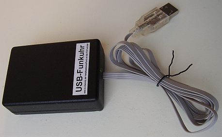
A DCF77 time signal receiver with USB connection.
Occasionally, radio-controlled alarm clocks get out of work, but the DCF77 receiving module is still intact. But why making a voltage shifter for connecting a serial port when there is a nice USB solution there? Here, a small 8-pin ATtiny45 is sufficient, filled with smart firmware called V-USB and AVR-CDC. With this firmware combination, the DCF77 receiver creates a serial port and is fully compatible to old-style true-serial-port ones. No software adaption is necessary.
However, one line will not work at all, and another one not within “Funkuhr.exe”. DCD, DSR, RI and RxD will work. CTS won't work. The receiver has to be activated using any of the three output “pins” of the emulated serial port. However, one of these lines will not work at all. TxD and DTR will work. RTS doesn't work.
The software installation procedure below is for Windows (2k, 2k3, XP, Vista, 7). Linux and Mac users should know what to do.
                           TPS71533DCKR
                             5╔═════╗4
3P3 ───┬────────────────────┬─╢O G I╟───┬── 5P (1)
      +│ 4,7µF              │ ╚╤═╤═╤╝   │
      ═╧═ ┌─────────────────┼────┘2     │
      ═╤═ │ 1╔═════╗╔═════╗8│ ╔═════╗   ▼ LED yellow
       ├──┘  ╢     ╚╝     ╟─┴─╢1,5kΩ╟─┐ ┬
       │    2║            ║7  ╠═════╣ │ │
SIG ───┼─────╢            ╟───╢ 47Ω ╟─┴─┼── D- (2)
       │    3║            ║6  ╠═════╣   │
ENA ───┼─────╢            ╟───╢ 47Ω ╟───┼── D+ (3)
       │    4║            ║5  ╠═════╣   │
       ├─────╢  ATtiny45  ╟───╢470Ω ╟───┘
       │     ╚════════════╝   ╚═════╝
GND ───┴─────────────────────────────────── G╧ (4)
┌──────────┐
│  DCF77   │                             ┌───────┐
│ receiver │                             │  USB  │
│  module  │                             └───────┘
└──────────┘ |
![[PCB top side]](lp-vorn.jpg)
![[PCB bottom side]](lp-hinten.jpg)
![[Soldered TPS71533]](lp-detail.jpg)
The Firmware is freeware (FunkUsb.c: Public Domain; V-USB part: GNU LGPL). The firmware contains a new approach for synchronization of internal RC oscillator, and lots of changes at AVR-CDC for support of virtual modem state lines.
Note that DOS software will not run with FunkUsb. Windows does not virtualize port addresses.
After installing the driver, the device will not automatically run nor a clock will automatically set. This is done with the next program, for example.
Driver installation for the COM port may be complicated!!
You can use any receiver software of your choice, but it must be Windows (not DOS) software that accesses a COM (not LPT) port.
Normally, the LED lights dimmed. On aerial signal (carrier attenuation) the LED lights up. For enabling this effect, the running receiver software must activate either TxD or DTR. In USB standby mode, the LED is off.
 With same schematic, a newer approach emulates a one-button joystick.
It has some pros and cons:
With same schematic, a newer approach emulates a one-button joystick.
It has some pros and cons:
Note: The Windows 98 Control Panel application refuses to work properly. For the same reason as joySetCapture() expects two levers. FunkUsb.exe uses joyGetPosEx() instead.
My „Funkuhr.exe“ application is extended to know this HID Interface.
Moreover: The firmware source code allows easily configurable port pins and is suited for both gcc3 and gcc4.
![[Screenshot]](dcf77-js.png)
Nevertheless, my dcf77-js.c can set the system clock. This source code doesn't depend on uncommon libraries, is easily compilable, and useful for setting the system clock of a Raspberry Pi.
The program uses /dev/input/js0 as default device. The one-and-only command-line parameter selects another joystick.
The program runs in one of two modes:
The archive contains an x86-64 binary image file.
See German version of this page for further details.