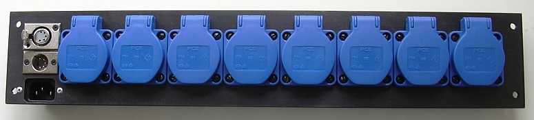
Einfacher DMX-Dimmer
Ein 8-Kanal-DMX-Dimmer mit Triacs, geeignet für die Ansteuerung
ohmscher und auch induktiver Lasten, im Gegensatz zum
DMX-Dimmer von Digital Enlightenment
(bei jenem retten Sicherungen die Triacs vor dem Tod durch Fehlsteuerung).
Die Betonung liegt auf einfach! Also geizig.
Es wurde alles weggelassen, was nicht wirklich nötig ist:
- Kein Differenzverstärker 75176 am Eingang,
dieser erfordert eine extra Stromversorgung.
Stattdessen direkter Eingang in Optokoppler,
dadurch partieller Terminierungseffekt wie bei IDE
- Kein Netztrafo für den Mikrocontroller.
Dieser frisst bloß Platz und Ruhestrom
- Keine Potenzialtrennung zu den Steckdosen.
Das erspart die MOC2032 (Opto-Triacs) und erleichtert wesentlich
die Erkennung des Strom-Nulldurchgangs,
der für jeden (möglicherweise induktiven) Verbraucher extra erforderlich ist.
Natürlich ist der DMX-Anschluss vom Netz getrennt.
- Minimaler Mikrocontroller ATtiny2313, alle Portpins belegt.
Dennoch Adressierbarkeit aller 512 DMX-Adressen (in Achterschritten)
- Kombinierter Nulldurchgangsdetektor- und Zündanschluss am Mikrocontroller
ohne Schutzmaßnahme.
Mikrocontroller sind mittlerweise billig.
Wenn's mal einen (auf Grund eines defekten Triac) abschießt,
kann man den nächsten stecken.
Eine IC-Fassung sollte allerdings vorgesehen werden, so kann der Controller
extern programmiert werden.
- Die Dioden D10..D17 sind notwendig, weil die Triacs einen
Ableitwiderstand von ca. 100 Ω zwischen Gate und „Kathode“ haben.
Es gibt sicherlich auch Triacs ohne diesen (störenden) Widerstand,
sind aber wahrscheinlich teurer.
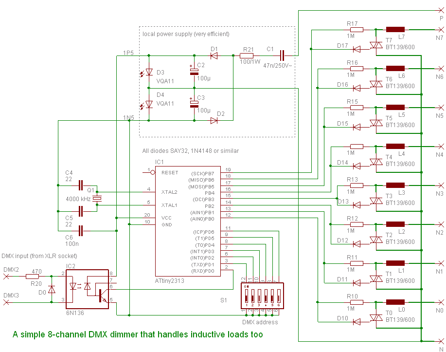
Schaltplan
Arbeitsweise
Der Mikrocontroller wird mit 3 V Betriebsspannung betrieben,
nämlich symmetrische ± 1,5 V.
An den Anschlüssen PB0 bis PB7 wird der Spannungs- bzw.
Stromnulldurchgang zur Synchronisierung auf die Netzfrequenz
als auch zur Festlegung des optimalen Zündzeitpunktes detektiert.
Die Widerstände R10 bis R17 sind so groß dimensioniert,
dass die Triacs T0 bis T7 nicht zünden,
jedoch, durch die Spannungsbegrenzung an den Triac-Gates ± 0,7 V
an den Eingängen bereit stehen.
Mit den Dioden erfolgt die Spannungsbegrenzung
für die negative Halbwelle an den Dioden D10..D17,
für die positiven Halbwellen an den Gateschutzdioden des Mikrocontrollers.
Alternativ könnte man zwei antiparallel geschaltete Dioden verwenden.
Zum Zünden eines Triacs wird ein Eingang kurzzeitig zum Ausgang
umprogrammiert.
Der Low-Pegel zündet über die internen Bahnwiderstände des Mikrocontrollers
den zugehörigen Triac im ersten oder dritten Zündquadranten.
Die mögliche Zündung je nach Halbwelle erlaubt die bessere Ausnutzung
des Netzteils, da die Energie durch den Kondensator voreilend bereit steht.
Mit den Dioden D10..D17 steht nur noch der dritte Quadrant zum Zünden
zur Verfügung.
Mit zwei antiparallelen Dioden gehen wiederum beide Quadranten.
Da dieser Dimmer 8 aufeinanderfolgende DMX-Adressen aus dem 512 Byte umfassenden
Adressraum benötigt, muss eine 6-bit-Adresse angelegt werden.
Dies erledigt der 6fach-DIL-Schalter mittels
mikrocontroller-interner Pull-Up-Widerstände.
Das symmetrische DMX-Signal wird dem schnellen Optokoppler 6N136
(billiger und Strom sparender als 6N137) zugeführt,
die „negative Halbwelle“ wird von einer Hilfsdiode gekappt.
Somit liegt eine partielle Terminierung mit 470 Ω vor, sodass einige solcher
Dimmer angeschlossen werden können.
Die Stromversorgung erfolgt mittels Blindwiderstand (Kondensator C1)
und Querregler.
Die Leuchtdioden arbeiten als Zener-Dioden, entweder als Bereitschaftsanzeige
oder als „Innenbeleuchtung“.
Der Quarzoszillator am Mikrocontroller ist unverzichtbar,
da durch die nicht ganz stabile Speisespannung kein genügend stabiler
Betrieb des internen (kalibrierbaren) RC-Oszillators möglich ist.
Für die Funktion des RS232-Empfängers sind mindestens 2 MHz erforderlich.
Je niedriger die Taktfrequenz, desto kleiner der Stromverbrauch des ATtiny,
und desto kleiner (und billiger) wird C1.
Warum nicht gleich ein USB-Dimmer?
USB-Dimmer sind, zumindest beim Einsatz von ATtiny/ATmega,
nur als Zwei-Chip-Lösung realisierbar.
Dazwischen befände sich genau jener Optokoppler wie bei dieser Lösung.
Ergo: USB-Dimmer sind genauso aufwändig wie ein
USB→DMX-Konverter
und ein DMX-Dimmer.
(Genau dafür ist ja DMX gemacht, für netzverbundene Schaltungen!)
Beim Einsatz von (teureren) Mikrocontrollern mit USB-Hardware bräuchte
man ein ganzes Rudel von Optokopplern, auch das wird teurer.
Firmware
Fehlt noch. Genauso wie der tatsächliche Aufbau und Test.